
Central injection unit
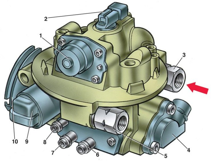
1 - fuel pressure regulator; 2 - nozzle; 3 - fuel supply fitting; 4 - throttle position sensor; 5 - fuel outlet to the tank; 6 – adsorber purge pipe; 7 – a branch pipe of ventilation of a crankcase of the engine; 8 - branch pipe for connecting an absolute pressure sensor; 9 - idle speed regulator; 10 - throttle drive sector from the pedal in the car
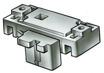
Absolute pressure sensor
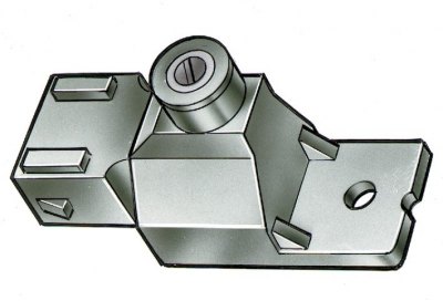
Octane potentiometer
Coolant temperature sensor
The coolant temperature sensor is a thermistor, (resistor whose resistance changes with temperature). The sensor is wrapped in the coolant outlet on the cylinder head. At low temperatures, the sensor has a high resistance (more than 100 ohm at -40°С), and at high temperature - low (177 Ohm at 100°C). The ECU calculates the coolant temperature from the voltage drop across the sensor. The voltage drop is high on a cold engine and low on a warm one. The coolant temperature affects most of the characteristics controlled by the ECU.
Air temperature sensor
The air temperature sensor wrapped in the bottom of the air filter housing is also a thermistor. It constantly measures the air temperature and monitors its change. When the air temperature drops, its resistance increases, and when it rises, it decreases.
When temperature fluctuates, the ECU monitors the voltage drop across the sensor and regulates the amount of fuel injected.
Absolute air pressure sensor
Absolute air pressure sensor (see fig. Absolute pressure sensor) fixed in the air inlet box, and connected by a hose to the branch pipe 8 (see fig. Central injection unit). It monitors the air pressure in the intake pipe, which changes as a result of changes in engine load and engine speed.
The sensitive element of the sensor is a miniature diaphragm with a resistor deposited on it. Depending on the air pressure, the tension of the diaphragm changes and the resistance of the resistor changes accordingly. The microcircuit built into the sensor converts this change in resistance into a change in voltage at the output of the sensor.
At idle, a relatively low signal voltage is generated at the sensor output (1-1.5 V). And at wide open throttle - the highest signal level (about 4-4.5 V), because in this case, the pressure in the intake pipe is equal to atmospheric.
The sensor takes into account barometric pressure, which allows the ECU to automatically make altitude adjustments to the fuel supply.
The ECU uses information from the MAP sensor to control fuel delivery and ignition timing. When the pressure in the intake pipe increases (the output voltage of the sensor increases) - the fuel supply is increased. When the pressure drops (sensor output voltage drops) – the fuel supply is reduced.
Oxygen concentration sensor
The oxygen concentration sensor is installed on the exhaust manifold. The oxygen contained in the exhaust gases reacts with the oxygen sensor, creating a potential difference at the output of the sensor. It varies from approximately 0.1 V (high oxygen content - lean mixture) up to 0.9 V (little oxygen - rich mixture).
For normal operation, the sensor must have a temperature of at least 360°C. Therefore, for quick warm-up after starting the engine, a heating element is built into the sensor.
By monitoring the output voltage of the oxygen concentration sensor, the control unit determines which command to adjust the composition of the working mixture to apply to the injectors. If the mixture is lean (low potential difference at the sensor output), then a command is given to enrich the mixture. If the mixture is rich (high potential difference) - a command is given to lean the mixture.
Speed sensor
The vehicle speed sensor is mounted on the transfer case between the speedometer drive and the tip of the speedometer drive flexible shaft. The principle of operation of the sensor is based on the Hall effect. The sensor outputs rectangular voltage pulses to the computer with a frequency proportional to the speed of rotation of the drive wheels.
Based on information from the sensor, the ECU sets the idle mode, and also turns off the cooling fan at high vehicle speeds.
Octane potentiometer
Octane potentiometer (see fig. Octane potentiometer) installed in the engine compartment on the wall of the air intake box and is a variable resistor. It outputs a signal for correcting the ignition timing to the electronic control unit. Adjustment of the octane potentiometer is carried out only at a service station using diagnostic equipment.
Throttle position sensor
Throttle position sensor 4 (see fig. Central injection unit) installed on the central fuel injection unit and connected to the throttle valve axis.
The sensor is a potentiometer, one end of which is supplied with a plus supply voltage (5 V), and the other end is connected to ground. From the third output of the potentiometer (from the slider) is the output signal to the electronic control unit.
When the throttle is turned, (from impact on the control pedal), the voltage at the output of the sensor changes. When the throttle is closed, it is lower than 0.7 V. When the throttle opens, the voltage at the sensor output rises and should be more than 4 V when the throttle is fully open.
By monitoring the output voltage of the sensor, the control unit adjusts the fuel supply depending on the throttle opening angle (those. at the request of the driver).
The throttle position sensor does not require any adjustment. control unit senses idling (those. full throttle closing) as a zero point.
Crankshaft position sensor
The crankshaft position sensor is an inductive type, designed to synchronize the operation of the control unit with the top dead center of the pistons of the 1st and 4th cylinders and the angular position of the crankshaft.
The sensor is installed on the cover of the camshaft drive opposite the setting disk on the generator drive pulley. The disc has 6 slots equally spaced around the circumference and one slot located 100 from one of them and serving to generate a synchronization pulse. As the crankshaft rotates, the slots change the sensor's magnetic field, creating voltage pulses at the sensor's output.
The ECU determines the crankshaft speed from the sensor signals and outputs pulses to the injectors.
Air conditioning request signal
If the car is equipped with air conditioning, the signal comes from the air conditioning switch on the instrument panel. In this case, the ECU receives information that the driver wants to turn on the air conditioner.
Having received such a signal, the ECU first adjusts the idle speed controller to compensate for the additional load on the engine from the air conditioning compressor, and then turns on the relay that controls the operation of the air conditioning compressor.