
Piston and connecting rod markings
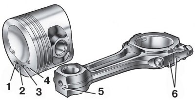
1 - arrow for orienting the piston in the cylinder; 2 - repair size; 3 - piston class; 4 - hole class for the piston pin; 5 - connecting rod class according to the hole for the piston pin; 6 - cylinder number
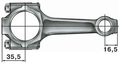
Places where it is allowed to remove metal when adjusting the mass of the upper and lower connecting rod heads
Pistons
Diameter of pistons of various classes, measured in a plane perpendicular to the pin axis at a distance of 55 mm from the piston bottom, mm:
class A | 81,965 – 81,975 |
class B | 81,975 – 81,985 |
class C | 81,985 – 81,995 |
class D | 81,995 – 82,005 |
class E | 82,005 – 82,015 |
According to the diameter of the hole for the piston pin, the pistons are sorted into three classes through 0.004 mm, as on other VAZ engines. Piston diameter classes and piston pin bores are stamped on the piston crown (see fig. Piston and connecting rod markings).
In the manufacture of the mass of pistons is strictly maintained. Therefore, when assembling the engine, it is not required to select pistons of the same group by weight.
On the bottoms of the repair pistons are marked in the form of a triangle or square. A triangle corresponds to an increase in the outer diameter of 0.4 mm, and a square to 0.8 mm.
The arrow on the bottom of the piston shows how to correctly orient the piston when it is installed in the cylinder. It should be directed towards the camshaft drive.
Piston pin
Piston pin floating type, i.e. rotates freely in the piston bosses and the connecting rod bushing. The pin is fixed in the piston with two steel retaining rings.
Connecting rod
A steel-bronze bushing is pressed into the upper head of the connecting rod. According to the diameter of the hole of this bushing, the connecting rods are divided into three classes through 0.004 mm (just like pistons). Class number 5 is stamped on the upper head of the connecting rod.
By the mass of the upper and lower heads, the connecting rods are divided into classes, marked with paint on the rod of the connecting rod. Connecting rods of the same weight class must be installed on the engine. You can adjust the mass of connecting rods by removing metal from the bosses on the heads to the minimum sizes of 16.5 and 35.5 mm (see fig. Places where it is allowed to remove metal when adjusting the mass of the upper and lower connecting rod heads).
Connecting rod bolts are pressed into the connecting rod. When disassembling the engine, it is not allowed to press out the bolts from the connecting rods.
Connecting rod classes by weight of the upper and lower heads
Mass of connecting rod heads, g | Class | Marking color | |
top | bottom | ||
186 ± 2 | 519 ± 3 | A | white |
525 ± 3 | B | blue | |
531 ± 3 | C | red | |
190 ± 2 | 519 ± 3 | D | black |
525 ± 3 | E | violet | |
531 ± 3 | F | green | |
194 ± 2 | 519 ± 3 | G | yellow |
525 ± 3 | H | brown | |
531 ± 3 | I | orange | |