
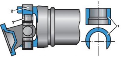
Pressing the bearing out of the elastic support
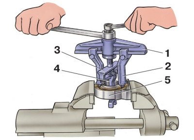
1 - bar A.40005/2; 2 - paws A.40005/11; 3 - puller А.40005/4; 4 - paws; 5 - elastic support
1. Apply marks (paint or core), which determine the relative position of the parts to be separated in order to connect them during assembly in the same position and keep the balance of the shafts unchanged.
2. Install the front driveshaft in a vise. Remove retaining rings.
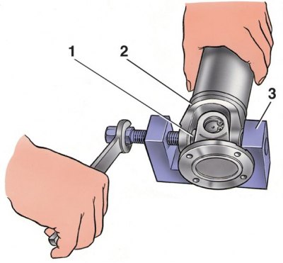
3. Press bearing housings 1 out of universal joint yoke 2 using tool 3 (clamp 67.7823.9522) or a punch with a hammer.
4. It is impossible to press out needle bearings in the joints of the new design in this way due to the increased thickness of the joint fork.
Pressing out the bearing housing
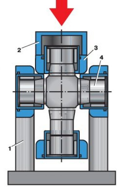
5. Install the cardan shaft of one of the universal joint yokes on the support 1 of the press. Through the special sleeve 2, use the press rod to move the other fork 3 of the hinge down until it stops against the crosspiece 4.
6. After turning the fork of the hinge by 1800, repeat the indicated operations, that is, move the other end of the fork down until it stops against the cross. When performing these operations, the opposite bearing of the cross 2 will partially come out of the fork hole and it will be possible to install the sleeve 1 with a side cut into the resulting gap between the fork and the cross.
7. Install the sleeve 1 on the spike of the cross, move the hinge fork down until the bearing 2 is pressed out.
8. Press out the other spider bearings using these techniques.
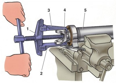
9. Unscrew the nut fastening the fork 3 of the cardan joint to the front shaft 4. Remove the fork with tool 1 (puller А.40005/1/5) (2 - puller levers).
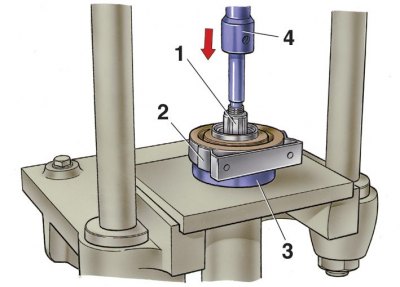
10. Under the press, using half-rings 3, remove from the front shaft 1 intermediate support 2 in combination with the bearing and dust deflector (4 - press punch).
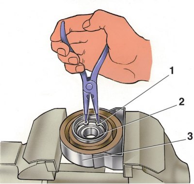
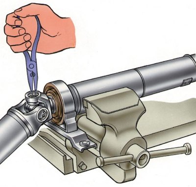
11. To disassemble the intermediate support, remove the retaining ring 1 (2 - bearing, 3 - elastic support).
12. Then press the bearing out of the bearing with the puller А.40005/2/4/11 (see fig. Pressing the bearing out of the elastic support).
13. Disassemble the rear shaft using the techniques described above.