
Details of the front driveshaft
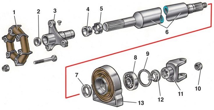
1 - elastic coupling; 2 - centering sleeve; 3 – flexible coupling flange; 4 - stuffing box; 5 – stuffing box holder; 6 - cardan shaft; 7 - dust deflector; 8 - bearing; 9 - retaining ring; 10 - nut; 11 - fork cardan joint; 12 - dust deflector; 13 - elastic support
Assembling the universal joint
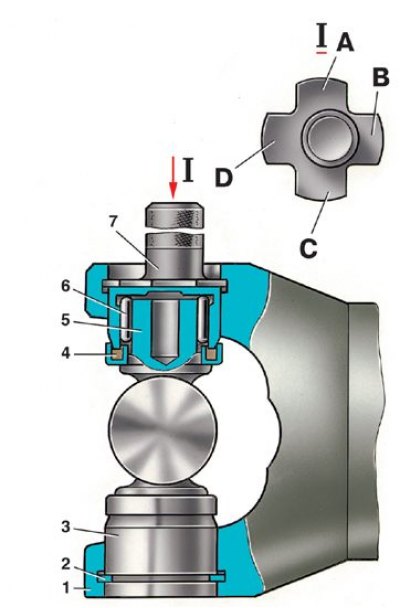
1 - fork cardan joint; 2 - retaining ring; 3 - bearing housing; 4 - stuffing box; 5 - spike of the cross; 6 - bearing needle; 7 - caliber 41.8734.4092; A, B, C, D - probe petals
1. Assemble cardan shafts in the reverse order of disassembly.
2. Apply FIOL-1 grease to splined joints.
3. When connecting parts, align the marks made on the detachable parts before disassembly.
4. After assembling the spline connection, pressing the stuffing box by 0.3–0.5 mm with an axial load, crimp the clip on the fork groove.
5. Tighten the front propeller shaft yoke nut with a torque wrench and caulk.
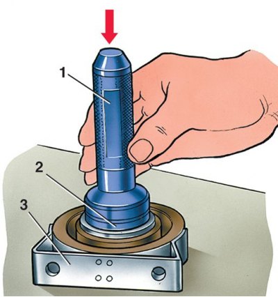
6. When assembling the intermediate support 3, press the bearing 2 with tool 1 (mandrel A.70045) and install a snap ring in the groove of the support.
7. Put on the rear end of the front propeller shaft dust deflector 7 (see pic. Details of the front driveshaft).
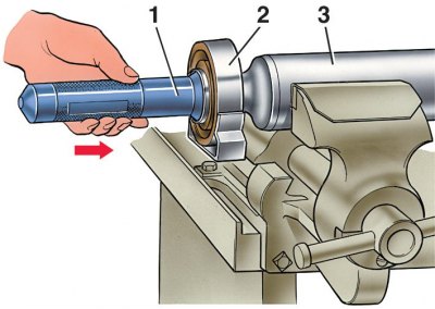
8. Then with tool 1 (mandrel A.4035) press support 2 with bearing (3 – a back part of a forward cardan shaft).
9. Put on the second dust deflector 12 (see pic. Details of the front driveshaft), press the fork 11 of the front propeller shaft onto the shaft and fix it with a nut.
10. Assemble the universal joint of the old design in the following order.
11. After removing the old thickened grease, fill the cavities in the spikes of the cross and lubricate the inner surface of the bearing housings with FIOL-2U grease (0.4–0.6 g per bearing).
12. Lubricate the spikes of the cross with a thin layer of grease so that an air cushion does not form during assembly. Insert the spikes of the cross into the fork.
13. Put the bearing housings with needles on the spikes of the cross and press them into the holes of the fork with a force of 7840 N (800 kgf).
14. Install the retaining rings in the grooves of the fork in their original places according to the marks.
15. Then check the axial free play of the spider, which should be 0.01–0.04 mm.
16. If the free play is greater than the specified value, replace one thinner circlip with a thicker one.
17. When replacing parts of the universal joint, select locking rings with caliber 41.8734.4092, which has four petals of different thicknesses (1.53mm; 1.56mm; 1.59mm; 1.62 mm).
18. To do this, install the retaining ring 2 (see fig. Assembling the universal joint) 1.56 mm thick.
19. When pressing bearings, when the cross rests against the bearing housing (in this case there are no gaps), using a feeler gauge caliber 4187.34.409, determine the distance between the bearing housing and the end face of the annular groove.
20. Depending on the measured distance, taking into account the axial clearance of 0.01–0.04 mm, insert a second circlip of the appropriate thickness. For example, if a petal passes 1.56 mm, then a 1.53 mm ring should be installed.
Attention! Retaining rings are supplied as spare parts of five (seven*) sizes (by thickness, mm), each having a specific color: 1.50 (1,45) * - natural; 1.53 (1,52) * - dark brown; 1.56 (1,56) * - blue; 1.59 (1,60) * - black; 1.62 (1,48) * - yellow; (1,64; 1,67) * - colors are not indicated and their thickness is determined by measurement.
21. If the dipstick is the thinnest (1.53mm) does not fit into the groove, replace ring 2 with another 1.50 mm.
22. If the dipstick is the thickest (1.62 mm) enters the groove with a gap, then replace ring 2 with another one, 1.62 mm thick.
23. After installing the retaining rings, hit the forks with a plastic-headed hammer. Under the action of impact and elastically compressed glands, the gap between the bottom of the bearing and the retaining ring is eliminated and gaps appear between the bearing housings and the ends of the cross spikes.
24. After assembly, check the ease of rotation of the forks of the hinge and the balance of the driveline.
25. The assembly of a universal joint with pressed sheet steel needle bearing housings has its own characteristics. The clearance between the bearing housing and the end face of the annular groove is measured with two gauges, one of which has a set of probe blades 1.45 thick; 1.48; 1.52; 1.56 mm, and the other - 1.60; 1.64; 1.67 mm.
26. If the stylus blade is the thinnest (1.45mm) is not included in the gap between the bearing housing and the end face of the annular groove, then the ring 2 (see fig. Assembling the universal joint) 1.56 mm thick, replace with another one 1.45 mm thick.
27. If the stylus tab is thickest (1.67mm) enters the gap loosely, then install a ring with a thickness of 1.67 mm into this gap, remove ring 2 and repeat the operations to select the thickness of the ring again.
28. If the feeler blade fits tightly into the gap, then install a ring in the groove, the thickness of which is equal to the size of the feeler gauge.
29. The force of pressing needle bearings into the holes of the forks must not exceed 10,000 N (1000 kgf).
30. Measure the gap with a feeler gauge from the side of the cardan shaft.
* For new design hinge.