




Open large image in new tab »
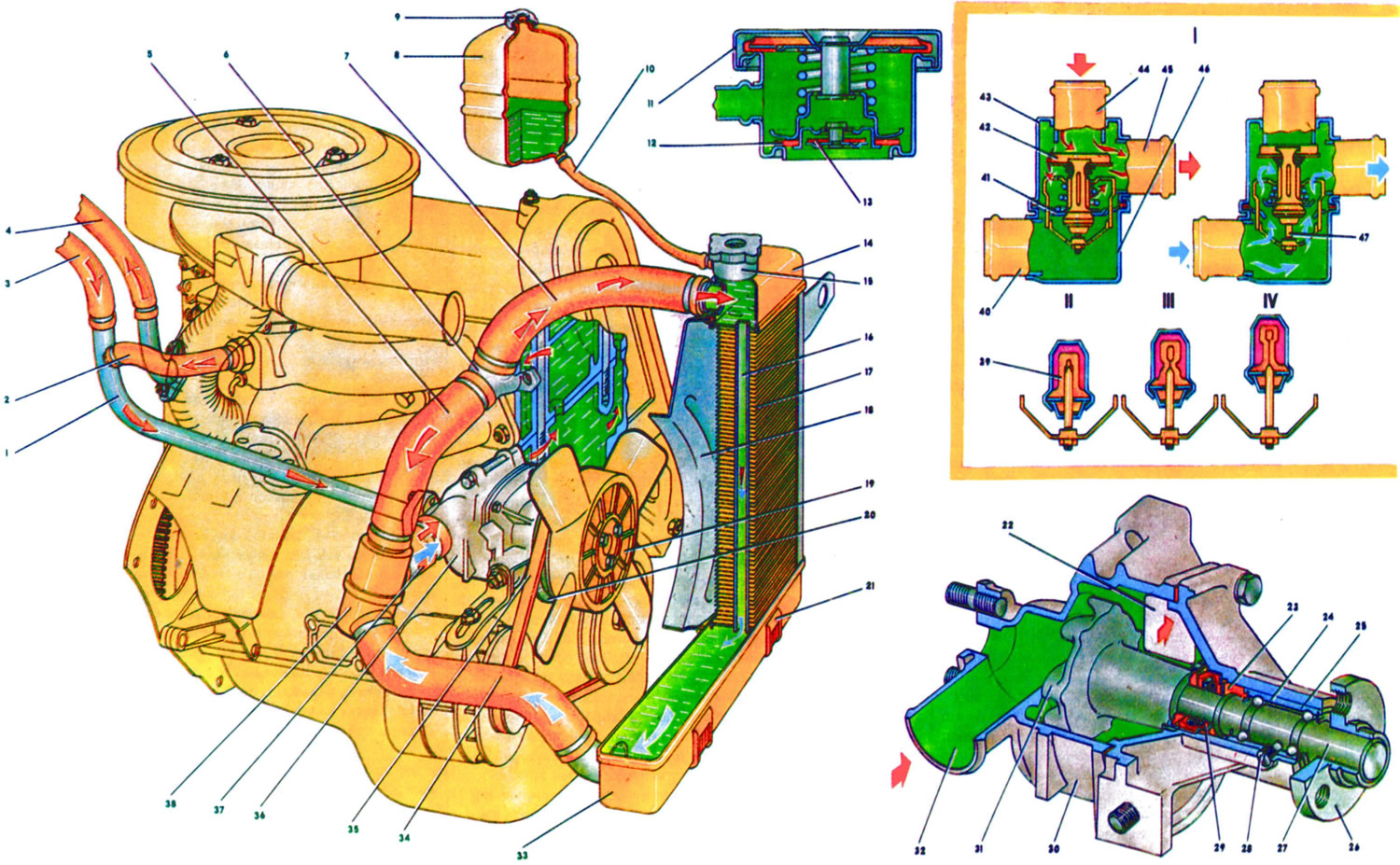
Fig. 7. 1. Pipe for draining liquid from the heater radiator to the coolant pump. 2. Hose for draining coolant from the inlet pipe. 3. Hose for draining coolant from the heater radiator. 4. Hose for supplying liquid to the heater radiator. 5. Thermostat bypass hose. 6. Cooling jacket outlet pipe. 7. Radiator inlet hose. 8. Expansion tank. 9. Tank cap. 10. Hose from the radiator to the expansion tank. 11. Radiator cap. 12. Outlet (steam) valve of the cap. 13. Inlet valve of the cap. 14. Upper tank of the radiator. 15. Radiator filler neck. 16. Radiator pipe. 17. Radiator cooling fins. 18. Fan shroud. 19. Fan. 20. Coolant pump drive pulley. 21. Rubber support. 22. Window on the side of the cylinder block for supplying coolant. 23. Oil seal cage. 24. Coolant pump shaft bearing. 25. Pump cover. 26. Fan pulley hub. 27. Pump shaft. 28. Lock screw. 29. Oil seal cuff. 30. Pump housing. 31. Pump impeller. 32. Pump inlet pipe. 33. Lower radiator tank 34. Radiator outlet hose. 35. Radiator belt. 36. Coolant pump. 37. Coolant supply hose to the pump. 38. Thermostat. 39. Rubber insert. 40. Inlet pipe (from the radiator). 41. Main valve. 42. Bypass valve. 43. Thermostat housing. 44. Bypass hose branch. 45. Hose branch for supplying coolant to the pump. 46. Thermostat cover. 47. Working element piston. I - Thermostat operation diagram. II - Liquid temperature less than 80°C. III - Liquid temperature 80-94°C. IV - Liquid temperature greater than 94°C.
The engine cooling system is liquid, closed type, with forced circulation of liquid. The capacity of the system is 9.85 liters, including the heating system of the body interior. The cooling system consists of the following elements: coolant pump 36, radiator, expansion tank 8, pipelines and hoses, fan 19, cooling jackets of the block and cylinder head.
When the engine is running, the liquid heated in the cooling jackets flows through the outlet pipe 6 along the hoses 5 and 7 into the radiator or thermostat, depending on the position of the thermostat valves. The coolant is then sucked in by the pump 36 and fed back into the cooling jackets.
The cooling system uses a special liquid TOSOL A-40 - an aqueous solution of antifreeze Tosol-A (concentrated ethylene glycol with anti-corrosion and anti-foaming additives with a density of 1.12-1.14 g/cm³). TOSOL A-40 is blue in colour, has a density of 1.078-1.085 g/cm³ and a freezing point of minus 40°C.
The coolant level is checked on a cold engine (at a temperature of plus 15-20°C) by the liquid level in the expansion tank 8, which should be 3-4 mm above the "MIN" mark.
The density of the liquid is checked with a hydrometer during vehicle maintenance. If the density of the liquid increases and the level is low, distilled water is added. If the density is normal, the liquid of the brand that is in the cooling system is added.
If the density of the coolant is reduced and the vehicle needs to be operated in the cold season, the fluid is replaced with a new one.
To control the coolant temperature, there is a sensor installed in the cylinder head and an indicator on the instrument panel. During normal engine operating temperature conditions, the indicator arrow is at the beginning of the red field of the scale within 80-100°C. When the arrow moves into the red zone, it indicates an increased engine thermal mode, which may be caused by problems in the cooling system (loose pump drive belt, insufficient coolant or thermostat malfunction), as well as difficult road conditions.
The fluid is drained from the system through drain holes closed with plugs: one in the left corner of the lower tank 33 of the radiator, the other in the cylinder block on the left in the direction of vehicle movement.
The car's interior heater is connected to the cooling system. Heated liquid from the cylinder head comes through hose 4 through the heater radiator tap, and is sucked out by pump 36 through hose 3 and tube 1.
The coolant pump is of the centrifugal type, driven from the crankshaft pulley by the generator drive V-belt.
The pump is attached to the cylinder block on the right side through a sealing gasket with bolts with a tightening torque of 22-27 N·m (2.2-2.7 kgf·m).
The body 30 and cover 25 of the pump are cast from an aluminum alloy. In the cover, in the bearing 24, which is locked with a screw 28, a shaft 27 is installed. Bearing 24 is double-row, non-separable, without an inner race. The bearing is filled with grease during assembly and is not lubricated further.
The impeller 31 is pressed onto the shaft 27 on one side, and the hub 26 of the pump drive pulley is pressed onto the other. The impeller end that contacts the sealing ring is hardened by high-frequency currents to a depth of 3 mm. The sealing ring is pressed against the impeller by a spring through a rubber cuff 29.
The gland is non-separable and consists of an external brass collar 23, a rubber cuff and a spring. The gland is pressed into the pump cover 25.
The pump body has an inlet pipe 32 and a window 22 towards the cylinder block for supplying coolant by the pump.
With normal tension of the pump drive V-belt, the belt deflection under a force of 100 N (10 kgf) should be within 10-15 mm.
Fan
Fan 19 is a four-bladed impeller made of plastic, which is bolted to the hub 26 of the pump drive pulley. The fan blades have a variable angle of installation along the radius and, to reduce noise, a variable pitch along the hub. For better efficiency, the fan is located in a casing 18, which is bolted to the radiator brackets.
Radiator and expansion tank. The radiator with the upper 14 and lower 33 tanks, with two rows of brass vertical tubes 16 and tinned cooling plates 17 is attached with four bolts to the front of the body and rests on rubber supports 21.
Filler neck 15 of the radiator is closed by plug 11 and connected by hose 10 to translucent plastic expansion tank 8. The radiator plug has inlet valve 13 and outlet valve 12, through which the radiator is connected by hose to the expansion tank. The inlet valve is not pressed against the gasket (gap 0.5-1.1 mm) and allows the coolant to flow into and out of the expansion tank when the engine is heating and cooling.
[The information is published on the website VazBook.ru]
When the liquid boils or the temperature rises sharply, due to the small throughput, the inlet valve does not have time to release the liquid into the expansion tank and closes, disconnecting the cooling system from the expansion tank. When the pressure increases when the liquid is heated to 50 kPa, the outlet valve 12 opens, and part of the coolant is diverted into the expansion tank.
The expansion tank is closed with a plug, which has a rubber valve that is triggered at a pressure close to atmospheric.
Since 1988, radiators with aluminum cores made of two rows of horizontal round aluminum tubes and aluminum cooling plates have been installed on the engines of VAZ-2105 and VAZ-2104 cars. The radiator is two-pass with plastic tanks and pipes for connecting hoses. One of the tanks has a partition. The radiator is disassemblable, the core is attached to the tanks through sealing rubber gaskets. To improve the efficiency of liquid cooling, the aluminum cooling plates are stamped with a notch, and plastic turbulators in the form of corkscrews are inserted into some of the tubes. All this ensures turbulent movement of air and liquid in the tubes.
It is important to remember that it is not recommended to use water as a coolant in the cooling system with aluminum radiators in order to prevent corrosion of the aluminum tubes.
Thermostat and operation of the cooling system The thermostat of the cooling system accelerates engine warming up and maintains the required thermal mode of engine operation. At the optimal thermal mode, the temperature of the coolant should be 85-95°C.
Thermostat 38 consists of body 43 and cover 46, which are rolled together with seat of main valve 41. Thermostat has inlet branch pipe 40 for intake of cooled liquid from radiator, branch pipe 44 of bypass hose 5 for bypass of liquid from cylinder head to thermostat and branch pipe 45 for supply of coolant to pump 36.
The main valve is installed in the thermoelement cup, in which the rubber insert 39 is rolled. In the rubber insert there is a polished steel piston 47, fixed on a fixed holder. Between the walls and the rubber insert there is a heat-sensitive solid filler. The main valve 41 is pressed by a spring to the seat. Two posts are fixed on the valve, on which the bypass valve 42 is installed, pressed by a spring.
Depending on the temperature of the coolant, the thermostat automatically turns the cooling system radiator on or off and bypasses the liquid through the radiator or bypasses it.
On a cold engine, when the coolant temperature is below 80°C, the main valve is closed, the bypass valve is open. In this case, the liquid circulates through hose 5 through bypass valve 42 into pump 36, bypassing the radiator (in a small circle). This ensures rapid engine warm-up.
If the temperature of the liquid rises above 94°C, the temperature-sensitive thermostat filler expands, compresses the rubber insert 39 and pushes out the piston 47, moving the main valve 41 to full opening. The bypass valve 42 closes completely. The liquid in this case circulates in a large circle: from the cooling jacket through hose 7 to the radiator and then through hose 34 through the main valve enters the pump, which again directs it to the cooling jacket.
Within the temperature range of 80-94°C, the thermostat valves are in intermediate positions, and the coolant circulates in the small and large circles. The opening value of the main valve ensures gradual mixing of the cooled liquid in the radiator, which achieves the best thermal mode of engine operation.
The temperature at which the main thermostat valve begins to open must be within 77-86°C, and the valve stroke must be at least 6 mm.
The start of the main valve opening is checked in a tank with water. The initial water temperature should be 73-75°C. The water temperature is gradually increased by 1°C per minute. The temperature at which the main valve stroke is 0.1 mm is taken as the start of the valve opening temperature.
The simplest check of the thermostat operation can be carried out by touch directly on the car. If the thermostat is working properly, after starting a cold engine, the lower radiator tank begins to heat up when the liquid temperature indicator arrow on the instrument panel is approximately 3-4 mm from the red zone of the scale, which corresponds to a coolant temperature of 80-95°C.