
In building 16 (pic. 147) four poles 17 are fixed with excitation windings, three of which are serial and one shunt. The housing together with covers 6 and casing 14 are tightened with two bolts. The anchor has an end collector. The rear end of the armature shaft rotates in a ceramic-metal bushing pressed into cover 15, and the front end - in a bushing pressed into the clutch housing.
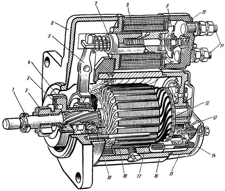
Pic. 147. Starter 39.3708: 1 - restrictive ring; 2 - drive gear; 3 - overrunning clutch roller; 4 - overrunning clutch; 5 - drive lever; 6 - cover on the drive side; 7 - relay armature; 8 - relay winding; 9 - contact plate; 10 - relay cover; 11 - contact bolts; 12—collector; 13 - brush; 14 - casing; 15 - back cover; 16 - body; 17 - pole; 18 - anchor; 19 - driving ring.
The starter connection diagram is shown in fig. 148. When the starter is turned on, the voltage from the battery through the auxiliary relay 3 type 113.3747-10 is supplied to both windings of the starter traction relay. After closing the contacts of the traction relay, the retracting winding is turned off.
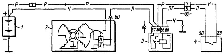
Pic. 148. Starter connection diagram: 1 - battery; 2 - starter; 3 - starter enable relay; 4 ignition switch.
Brief technical characteristics of the starter:
- Rated power, kW - 0.9
- Current consumption, A:
- at maximum power, no more than - 230
- in the inhibited state, no more than - 310
- at idle, no more than - 60