




- Nominal power, kW — 1.3
- Current consumption at maximum power, A, no more than - 260
- Current consumption in the braked state, A, no more than - 500
- Current consumption at idle, without relay, A, no more than - 60
The starter type 29.3708 is a DC electric motor with mixed excitation, left rotation, with an electromagnetic two-winding traction relay. It is used to start the engine, installed on its left side (front, if you look in the direction of the car) and is attached to the clutch housing with a flange using three studs.
The main components of the starter are the housing or stator 16 (figure 103) with excitation windings, anchor 18 with overrunning clutch 4, cover 6 on the drive side with lever 5, cover 14 on the collector side with brush holders and traction relay. Covers 6, 14 and the housing are connected by two tie bolts.
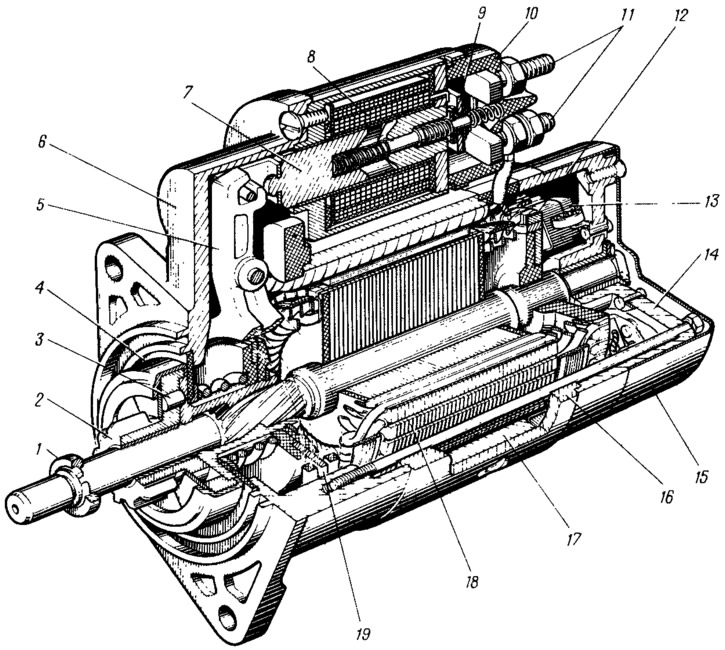
Figure 103. Starter:
1 - limiting ring; 2 - drive gear; 3 - roller of the overrunning clutch; 4 - overrunning clutch; 5 - drive lever; 6 - drive side cover; 7 - relay anchor; 8 - relay winding; 9 - contact plate; 10 - relay cover; 11 - contact bolts; 12 - collector; 13 - brush; 14 - cover from the collector side; 15 - casing; 16 - body; 17 - stator pole; 18 - anchor; 19 - leash ring.
The housing is made of soft strip steel rolled into a cylinder and welded at the joint. Four steel poles 17 are fixed with screws inside the housing, onto which the winding coils are put. The housing together with the coils and poles forms the stator. Three stator coils (series) are connected to the armature winding in series, and one (shung) is connected in parallel. Therefore, the excitation of the starter is mixed. It ensures a relatively low rotation frequency of the armature at idle, which reduces wear of the bearing bushings, facilitates the operating conditions of the overrunning clutch and prevents the armature from running away.
The main current consumed by the starter flows through the series coils and the anchor winding. Therefore, they are wound with copper tape with a large cross-section. A comparatively small current flows through the shunt coil, which depends mainly on the voltage of the storage battery. Therefore, the shunt coil is wound with copper wire in enamel insulation. The coils are braided with cotton tape and impregnated with varnish.
Anchor 18 consists of a shaft onto which a core made of electrical steel plates is pressed, and a commutator 12. A winding made of copper tape is placed in the grooves of the core. The ends of the winding are soldered to the commutator plates. The anchor shaft rotates in two metal-ceramic bushings impregnated with oil. The rear bushing is pressed into cover 14, and the front one is located in the clutch housing. The front end of the anchor shaft enters this bushing when the starter is secured to the clutch housing.
The starter uses a collector of the end type. It is a plastic disk in which copper contact plates of the collector are poured. The use of the end collector made it possible to reduce the length of the starter and its weight. In addition, such a collector contributes to more stable and long-term operation of the brush contact.
The starter drive is mounted on the front end of the armature shaft, consisting of a roller overrunning clutch and gear 2. The purpose of the overrunning clutch is to transmit torque from the starter armature shaft to the flywheel ring gear via gear 2 when starting the engine, and after starting, when operating in overrunning mode, to prevent torque from being transmitted from the flywheel to the armature. Otherwise, the armature winding may come out of the core slots due to "runaway" - excessively high rotational speed of the armature by the flywheel of the running engine.
The overrunning clutch consists of an outer ring with rollers 3 and an inner ring, combined with the gear 2 of the drive. In the outer ring there are three grooves of variable depth. In the deeper part of the groove the rollers can rotate freely, in the shallower part they are wedged between the outer and inner rings. The rollers are pressed into the shallower part of the groove by springs.
Covers 6 and 14 are cast from an aluminum alloy. Four brush holders with copper-graphite brushes are riveted to cover 14 from the inside. Two brush holders with positive brushes are insulated from the cover by textolite washers and bushings. The other two brush holders with negative brushes are riveted directly to the cover, i.e. connected to the "ground".
In cover 6, a plastic lever 5 is mounted on the axle, transmitting the traction force from the relay to the starter drive. The ears of the drive ring 19, mounted on a plastic centering disk, enter the grooves of the lever. This disk, together with the limiting ring and buffer spring, are secured with a locking ring on the hub riveted to the outer ring of the overrunning clutch 4.
The traction relay, attached with three screws to cover 6, serves to engage the drive gear with the flywheel crown and to close the power supply circuit of the anchor and stator windings. The relay has two windings: pull-in and holding, wound in one direction. The beginnings of the windings are soldered to the "50" plug on the relay cover. The end of the holding winding is welded to the relay flange (i.e. connected to the "ground"), and the end of the pull-in winding is connected to the lower contact bolt of the relay.
Figure 104 shows the starter activation diagram using auxiliary relay 6 type 113.3747-10, installed in the engine compartment on the front shield. At the beginning of the production of VAZ-2108 cars, this relay was not installed, and the voltage from the ignition switch was supplied directly to the starter traction relay.
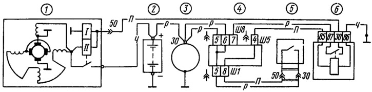
Figure 104. Starter connection diagram:
1 - starter; 2 - battery; 3 - generator; 4 - mounting block; 5 - ignition switch; 6 - starter relay.