




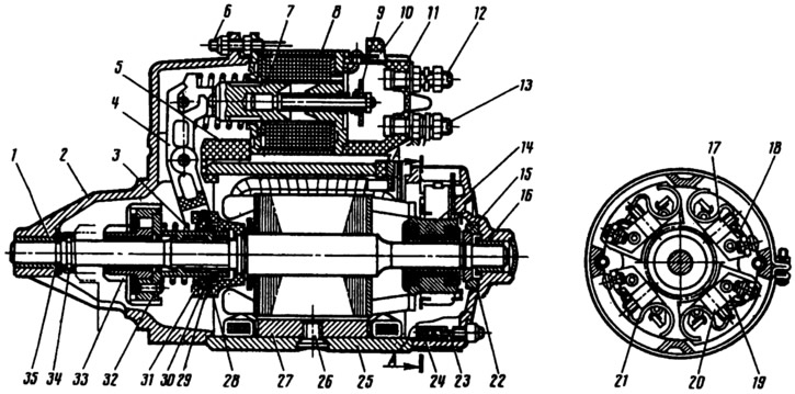
Fig. 232. Starter ST-221:
1 - bearing bushing; 2 - starter cover on the drive side; 3 - buffer spring; 4 - drive lever; 5 - rubber plug; 6 - relay clamp bolt; 7 - relay anchor; 8 - relay yoke; 9 - contact plate; 10 - plug "50" of the relay winding output; 11 - relay cover; 12 - Upper contact bolt; 13 - lower contact bolt; 14 - collector; 15 - anchor brake disc; 16 - anchor bearing sleeve; 17 - negative brush; 18 - negative brush holder; 19 - positive brush holder; 20 - floor (suspicious brush; 21 - brush spring; 22 - brake disc cover; 23 - tie rod; 24 - cover from the collector side; 25 - body; 26 - pole mounting screw; 27 - stator pole; 28 - drive gear travel limiter; 29 - limiting disk; 30 - leash ring; 31 - centering disk; 32 - overrunning clutch; 33 - drive gear; 34 - limiting ring; 35 - adjusting washers.
The covers and the starter housing are pulled together by two studs 23, which are screwed into the cover 2. Four poles 27 are installed in the housing 25 - two with series windings included in the circuit in series with the anchor, and two with tung windings (coils) included in parallel.
The starter anchor consists of a shaft, a core with a winding and a collector 14. The anchor shaft rotates in two porous metal-ceramic bushings 1 and 16, pressed into the starter covers and impregnated with oil. The axial free play of the anchor shaft is regulated by selecting washers 35 and should be within 0.07-0.7 mm. A starter drive is installed on the front end of the anchor shaft, consisting of a roller clutch 32 of free play and a gear 33.
Four brush holders with copper-graphite brushes are riveted to the cover 24. Two brush holders 19 are insulated from the cover by plastic plates. These are the brush holders of the positive brushes. The terminals of the series stator coils are connected to them. The other two brush holders 18 are attached directly to the cover and, therefore, are connected to the body. The terminal of the shunt coils is connected to one of them.
(The material is posted on the online resource www.VAZbook.ru)
The starter traction relay is attached to cover 2, consisting of an anchor 7, a winding, a contact plate 9 and a cover 11 with contact bolts 12. The traction relay switches on the starter and engages gear 33 with the flywheel ring gear. Since 1983, a traction relay with two windings has been used - a pull-in and a holding winding. When the starter is switched on, both windings work first. And after the traction relay contacts close, the pull-in winding is disconnected.
Since 1986, some vehicles have been equipped with a starter of type (model) 35.3708, which has an end collector, as well as three series stator windings and one shunt winding. The end collector is made in the form of a plastic disk with copper plates cast into it. Otherwise, the design of the 35.3708 starter is the same as that of the ST-221 starter.
The starter connection diagram is shown in Fig. 233. It is the same on VAZ-2105, -2104 cars. Since 1986, an additional relay 4 type 113.3747-10 has been included in the diagram, which is installed on the right wheel mudguard in the engine compartment. Before 1986, voltage from plug 50 of the ignition switch was supplied directly to plug 50 of the starter traction relay.
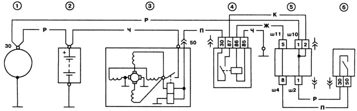
Fig. 233. Starter connection diagram:
1 - generator; 2 - battery; 3 - starter; 4 - additional starter relay; 5 - mounting block; 6 - ignition switch.