




- three or two jaw puller;
- mandrel from the cup puller kit for pressing out the front bearing.
Disassembly
1. Remove the generator from the car (see above).
2. Remove the voltage regulator and capacitor (see "Voltage Regulator and Capacitor - Checking and Replacing").
3. With a spanner by 8 mm unscrew the three bolts connecting the stator winding terminals to the rectifier unit (1), and another bolt securing the rectifier unit (2) (remember how the isolating and thrust washers are installed).
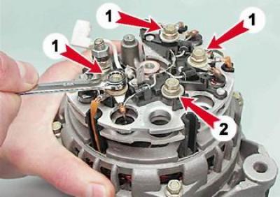
4. Carefully bend the stator winding terminal wires to the side.
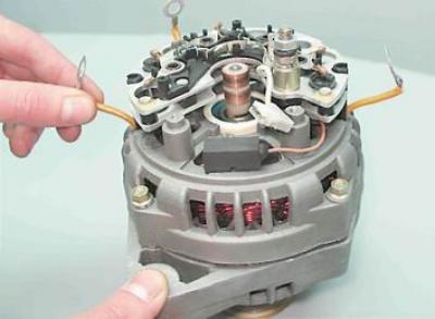
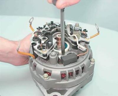
5. Using a Phillips screwdriver, unscrew the screw securing the capacitor.
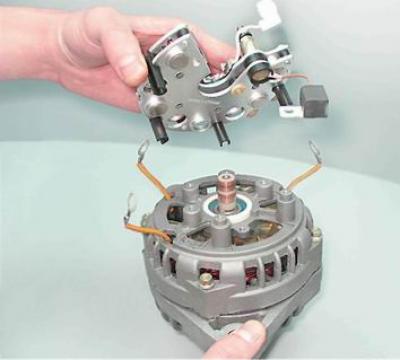
6. Remove the rectifier unit together with the capacitor. Using a socket wrench by 10 mm unscrew the two nuts of the contact bolt. Remove the distance and insulating bushings from the bolt, remove the bolt from the rectifier unit and remove the capacitor tip from the contact bolt.
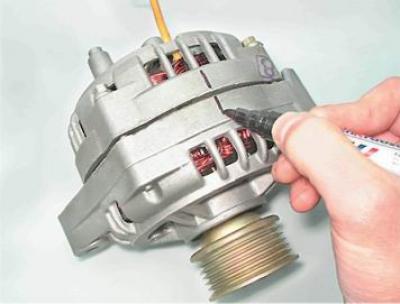
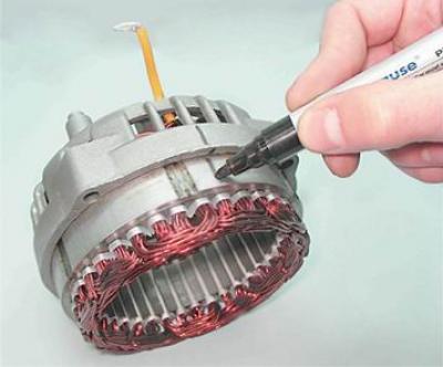
7. Using a marker, mark the relative positions of the front and rear covers of the generator (to simplify assembly).
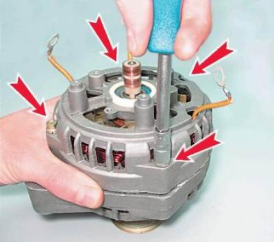
8. With a socket wrench by 8 mm we unscrew the four bolts that hold the front and rear covers of the generator together.
9. Using a slotted screwdriver, carefully move the generator covers apart.
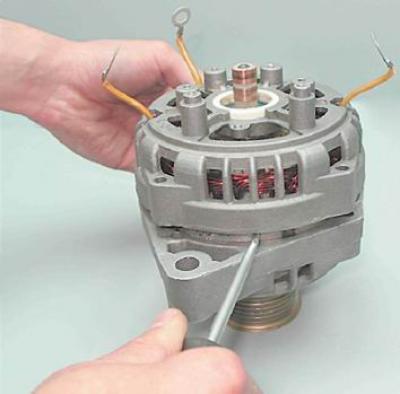
10. Disconnect the rear cover together with the stator winding from the front cover.
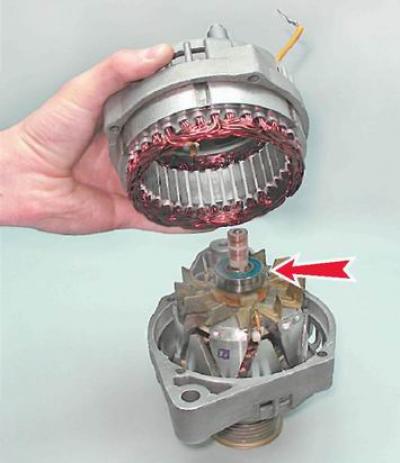
Recommendation. To determine the technical condition of the rear bearing, rock it from side to side and vigorously rotate its outer ring. The bearing should not have significant play, and the ring should rotate freely without jamming or extraneous noise. A faulty bearing must be replaced.
11. Using a marker, make a mark on the stator (to indicate its position relative to the back cover).
[The article is taken from an online resource VazBook.ru]
12. Remove the stator from the rear cover of the generator.
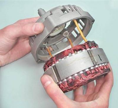
Recommendation. To determine the technical condition of the front bearing, hold the pulley with your hand, swing it from side to side and rotate the front cover. If the bearing is jammed, has significant play, or makes noise when the cover is rotated vigorously, it must be replaced.
Advice. The manufacturer recommends changing the front rotor bearing together with the front generator cover, as it is rolled into the cover. However, considering that the cost of the bearing is significantly lower than the cost of a new front cover and especially the generator assembly, it is advisable to press out and replace the faulty bearing.
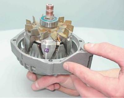
13. If it is necessary to replace the front bearing of the generator with a socket wrench by 24 mm we unscrew the pulley mounting nut, holding the pulley with sliding pliers.
14. Remove the pulley with the spring (3) and flat washer (2), and the spacer sleeve (1) from the rotor shaft.
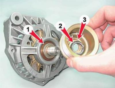
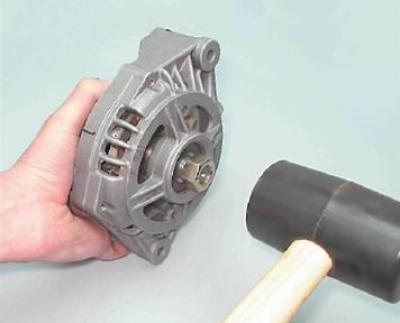
15. Screw the pulley mounting nut onto the rotor shaft thread (flush with end). Using a rubber-headed hammer, press the rotor out of the front bearing on the nut.
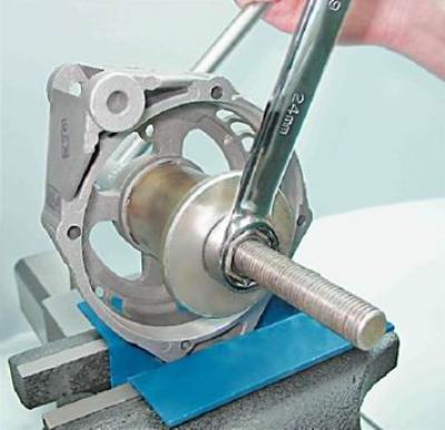
16. Install the front cover in a vice (the jaws of the vice should be fitted with soft metal pads).
17. Having selected suitable mandrels from the cup puller kit, press the bearing out of the seat in the front cover.
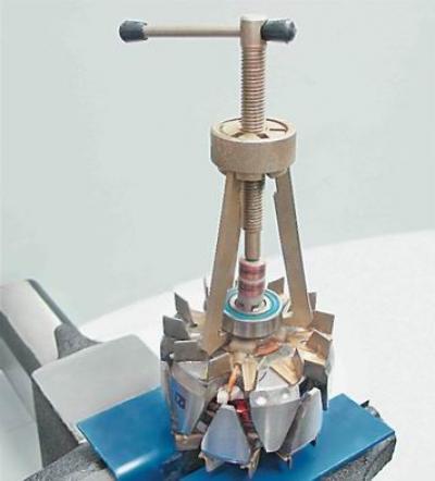
18. If it is necessary to replace the rear generator bearing, secure the rotor in a vice with soft pads on the jaws. Use a universal puller to press the rear bearing off the rotor shaft.
Examination
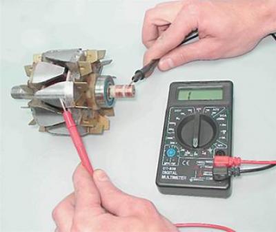
1. Check the stator windings: a) by applying the ohmmeter probes to the rotor slip rings, check the excitation winding for breakage. The resistance of a serviceable excitation winding should be 5-10 Ohm;
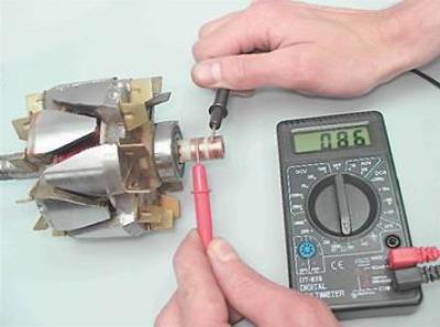
b) by connecting the ohmmeter probes to any contact ring and to the rotor, we check the excitation winding for short circuit to ground. If the rotor winding is in good condition, the ohmmeter should show infinite resistance.
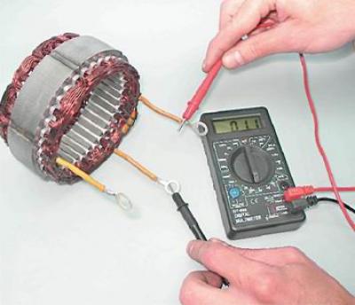
2. Check the stator windings: a) alternately connecting the ohmmeter probes to the stator winding terminals, check the winding for a break. If there is no break, the ohmmeter will show low electrical resistance (about 10 Ohm);
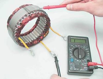
b) by connecting the ohmmeter probes to any terminal of the winding and to the stator, we check the stator winding for short circuit to ground. If there is no short circuit, the ohmmeter should show infinite resistance.
3. Check the rectifier unit:
Note: A good semiconductor diode conducts current in one direction only. A diode is faulty if it does not conduct current or conducts current in both directions.
a) connect the positive lead of the ohmmeter (in diode test mode) to the common bus of the auxiliary diodes (1), and the probe of the negative terminal to the terminal of the diode being tested (2). A serviceable diode should not pass current (resistance tends to infinity);
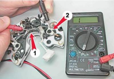
b) swap the tester probes. If the diode is working properly, the ohmmeter should show resistance (several hundred ohms). We check the other two auxiliary diodes in the same way;
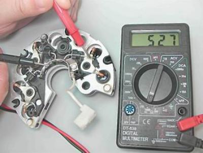
c) connect the probe of the negative terminal of the ohmmeter to the plate of the rectifier block, into which the diode being tested is pressed, and the probe of the positive terminal to the terminal of the diode. A serviceable diode should not pass current (resistance tends to infinity);
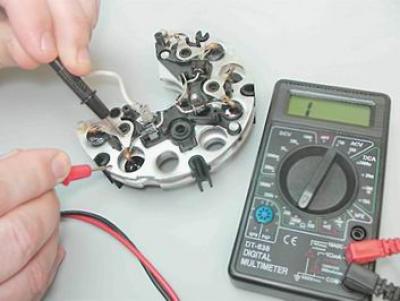
d) swap the tester probes. If the diode is working properly, the ohmmeter should show a resistance of several hundred ohms).
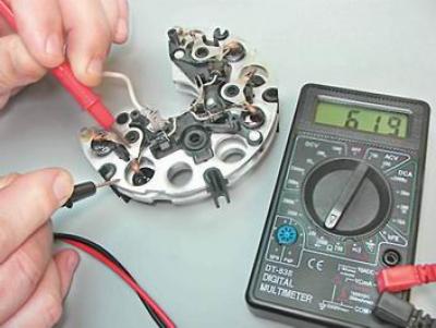
We check other power diodes in the same way.
A faulty rotor or stator must be replaced. If one or more diodes in the rectifier unit are faulty, the unit as a whole must be replaced.
Assembly
Warning! Before pressing the front alternator bearing into place, it is necessary to check the bearing seat and, if necessary, use a knife or scraper to restore the chamfer where the edges of the hole have remained dented. When pressing the front bearing into the cover, the force must be transmitted only to the outer ring of the bearing.
1. Having selected suitable mandrels from the cup puller kit, press the new front bearing into the seat in the front cover until it stops.
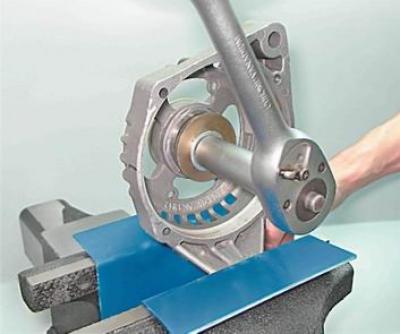
Warning: When performing the following operation, use only light hammer blows. Strong blows may crack the cover, which is made of fragile aluminum alloy.
2. Using a hammer and a steel punch of a suitable diameter, restore the bearing crimp in the cover.
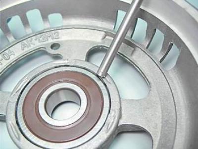
Warning! Before installing the rear generator bearing, make sure that the rotor shaft is securely clamped in a vice. Place a wooden block of suitable size under the rotor shaft to avoid damaging the front rotor impeller during pressing. To avoid damaging the bearing, only strike the inner ring.
3. Using a piece of pipe of a suitable diameter (you can use a deep head by 19 mm) we press the new bearing onto the rotor shaft until it stops.
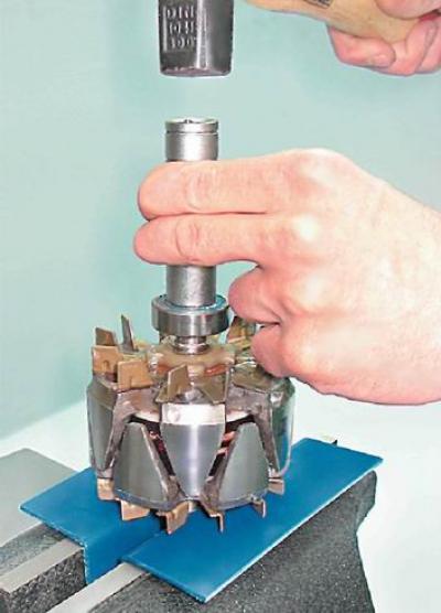
Further assembly of the generator is carried out in the reverse order. In this case, we align the marks applied to the covers and the generator stator. Finally, we tighten the tie bolts evenly, crosswise, in several steps of half a turn. Having tightened the bolts, we make sure that the rotor rotates easily (the rotor may jam due to the covers being skewed). Before tightening the stator winding mounting bolts, make sure that insulating washers are installed under their heads.
Warning: When installing the voltage regulator, do not apply lateral force to the brushes.