
Generator disassembly
Remove cover 8 (pic. 9-13), by releasing the latches that connect it to the back cover. Unscrew the screws securing the brush holder 12 to the rear cover assembly with the voltage regulator and remove it. Disconnect the wire from the outlet «D+» voltage regulator.
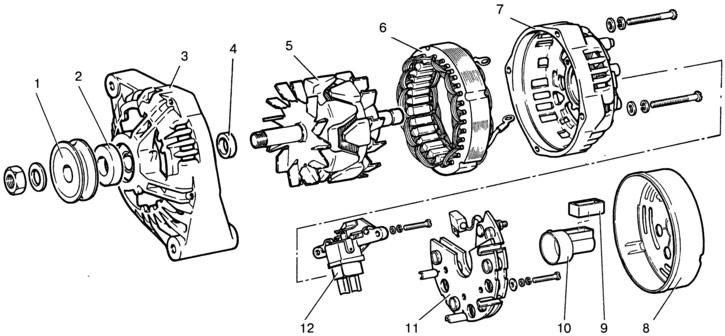
Pic. 9-13. Generator details:
1 - pulley; 2 - washer; 3 - front cover; 4 - remote ring; 5 - rotor; 6 - stator; 7 - back cover; 8 - casing; 9 - gasket; 10 - protective sleeve; 11 - rectifier unit with a capacitor; 12 - brush holder with voltage regulator.
Remove the protective sleeve 10 together with the gasket 9. Remove the rectifier unit with the capacitor from the rear cover, to do this, unscrew the screws securing the phase leads of the stator winding and the screw securing the capacitor to the cover. After that, if necessary, you can disconnect the capacitor from the rectifier unit by unscrewing the nut that secures the capacitor wire to the terminal «B+» rectifier block.
Turn out four coupling screws and disconnect a back cover 7 with a stator 6 from a front cover 3 with a rotor 5. Disconnect the stator from a back cover. If necessary, remove the sleeve with the rear bearing of the rotor shaft from the rear cover.
Clamp the rotor in a vice and use a socket wrench to unscrew the pulley fastening nut 1. Remove the pulley, washer 2, front cover and spacer 4 from the rotor shaft.
The generator is assembled in the reverse order of disassembly. The spring washer of the pulley with the convex side should be in contact with the nut.
Replacing the voltage regulator or brushes
The voltage regulator assembly with the brush holder is a non-separable unit. Therefore, if the voltage regulator fails or the brushes are worn out (protrude from the brush holder by less than 5 mm), the entire node is replaced.
Rotor bearing replacement
The front rotor shaft bearing is pressed and rolled into the front cover. Therefore, in the event of its failure, it is necessary to replace the front cover assembly with the bearing.
The rear bearing is pressed onto the rotor shaft. To replace it, it is necessary to remove the bearing from the rotor shaft with a puller and press a new bearing on the press.
Replacement of additional diodes
To replace, unsolder the leads of the damaged diode and carefully remove it from the plastic holder, avoiding sharp blows to the rectifier unit. Then clean the epoxy residue from the diode installation site, install and solder a new diode.
Solder the output of the diode with a color mark to a common bus. After soldering, glue the body of the diode to the holder with epoxy.