
Disassembly and assembly of the generator
Loosen the screws and remove the brush holder 1 (pic. 231) assembled with the regulator 21 and the capacitor 19. Unscrew the nuts of the coupling bolts 13 and remove the cover 10 of the generator together with the rotor. Clamp the rotor in a vice, unscrew the pulley nut and remove the pulley from the rotor shaft with a puller 02.7823.9504. Remove the segment key from the groove on the shaft and remove cover 10.
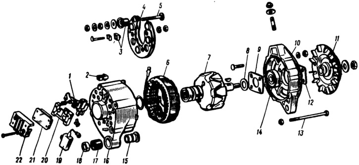
Pic. 231. Details of the G-222 generator:
1 - brush holder; 2 - block of the neutral wire plug; 3 - insulating bushings of the contact bolt; 4 - rectifier block; 5 - contact bolt: 6 - stator; 7 - rotor; 8 - washer; 9 - inner washer for fastening the bearing; 10 - cover on the drive side; 11 - pulley; 12 - outer washer for fastening the bearing; 13 - coupling bolt; 14 - rotor bearing; 15 - clamping sleeve; 16 - cover from the side of slip rings; 17 - buffer sleeve; 18 - bushing; 19 - capacitor; 10 - base; 21 - voltage regulator; 22 - casing.
Puller 02.7823.9504 consists of two steel half-rings, which are inserted into the pulley groove, and a conventional puller. The paws of the puller are captured by the half rings, and the bolt rests against the end of the generator shaft. The half rings have the same section as the alternator drive belt. On the one hand, they are hinged, and on the other hand, they are equipped with levers that are compressed by hand when the pulley is removed.
Unscrew the nuts of the screws connecting the valve tips to the stator winding leads, remove the zero drive plug from the block 2 and remove the stator 6 from the cover 16 of the generator. Unscrew the nut of the contact bolt 5 and remove the rectifier unit.
Generator 37.3701 is disassembled in the same order. Disconnect the wire from the plug first «IN» voltage regulator. Then disconnect the regulator and capacitor wires from the terminal «30» generator and unscrew the screws securing the voltage regulator. To avoid breaking the brushes when removing the brush holder, insert a screwdriver blade between the regulator housing and the brush holder and slide the regulator partially out of the generator, leaving the brush holder in place. After that, tilt and remove the regulator together with the brush holder from the generator. Remove the capacitor by unscrewing the fixing screw. Further disassembly of the 37.3701 generator is similar to the disassembly of the G-222 generator.
Assemble the generator in reverse order. The misalignment of the holes in the paws of the generator covers should be no more than 0.4 mm. Therefore, during assembly, it is necessary to insert a stepped cylindrical test mandrel into these holes, having a diameter of 12 mm on one side and 22 mm on the other. The convex side of the pulley spring washer must be in contact with the nut. Tighten the pulley nut with a torque of 3.9–9.0 kgf·m.
When assembling the generator 37.3701, in order to avoid breakage of the brushes, before installing the regulator with the brush holder in place, do not fully insert the brush holder into the regulator, but only partially push it in and insert it into the generator in this form. After installing the brush holder in place in the generator cover, lightly press the regulator to slide it into the generator.
Brush holder replacement
If the brushes are worn out and protrude from the brush holder by less than 5 mm, then replace the brush holder with brushes. Before installing a new brush holder in place, blow out the socket in the generator from coal dust and wipe it from oil mixed with coal dust.
Rotor bearing replacement
To remove the defective bearing from the cover on the drive side, unscrew the nuts of the screws tightening the bearing fastening washers, remove the washers with screws and press the bearing out on a hand press. If the nuts do not loosen (the ends of the screws are punched), then cut off these ends.
It is only possible to install a new bearing in the generator cover if the bearing hole is not deformed. The hole diameter should not exceed 42 mm. If the hole is oversized or deformed, replace the cap with a new one.
Press the bearing into the cover on a press and then clamp it between two washers tightened with screws and nuts. After tightening the nuts, unscrew the ends of the screws.
When replacing the rotor bearing on the slip ring side, replace the cover at the same time, because if the bearing is damaged, the socket in the cover is also damaged.
Replacement of additional generator diodes 37.3701
To replace, unsolder the leads of the damaged diode and carefully remove it from the plastic holder, avoiding sharp blows to the rectifier unit. Then clean the epoxy residue from the diode installation site, install and solder a new diode. The output of the diode with a color mark is soldered to the terminals of the valves. After soldering, glue the body of the diode to the holder with epoxy.