




- keys "10", "17", "19"
- screwdrivers
- universal puller
Remove the generator from the vehicle (see subsection 8.2.1.).
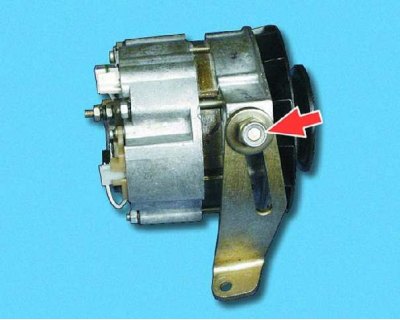
1. Loosen the nut and remove the adjusting bar.
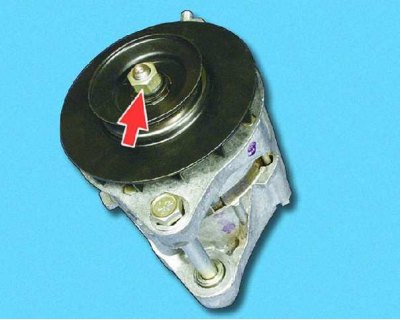
2. Loosen the mounting nut while holding the pulley from turning (see recommendation), and remove the pulley together with the fan impeller. Remove the woodruff key from the armature shaft.
Recommendation for surgery 2
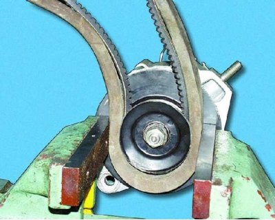
The manufacturer recommends holding the pulley from turning with a special device. If there is no device, you can do it this way:
1. Put the alternator belt on the pulley and another belt of a larger cross-section on top of it, so as not to crush the pulley.
2. Clamp the pulley with belts in a vice and unscrew the fastening nut.
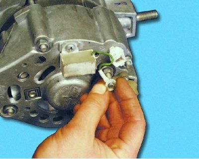
3. Unscrew the nut and disconnect the capacitor wire from the generator terminal "30".
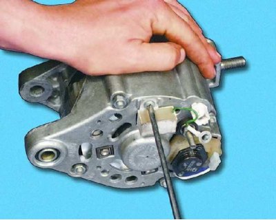
4. Loosen the screw and remove the capacitor.
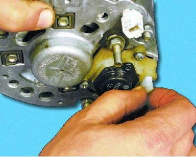
5. Disconnect the connector with the wire from the brush holder.
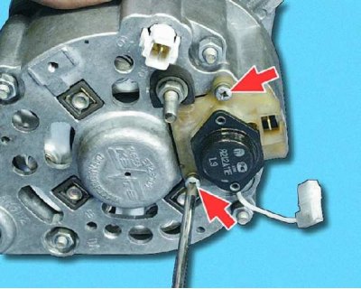
6. Remove the two screws securing the brush holder.
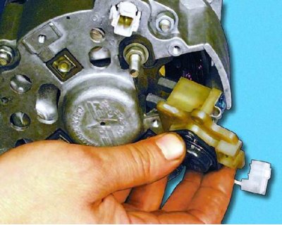
7. Remove the brush holder with the voltage regulator.
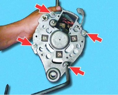
8. Unscrew the four mounting nuts and...
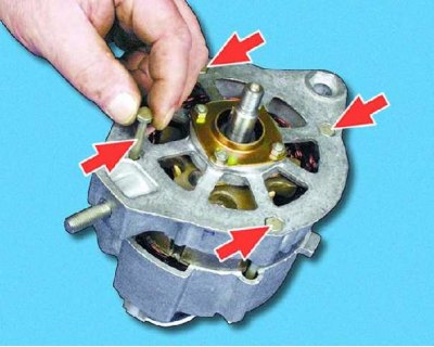
9....remove the four tie bolts.
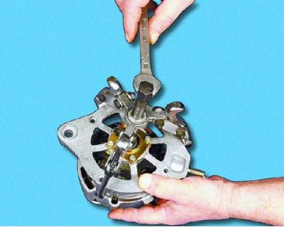
10. Using a puller, remove the cover from the drive side of the armature shaft.
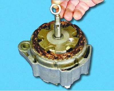
11. Remove the spacer sleeve from the armature shaft.
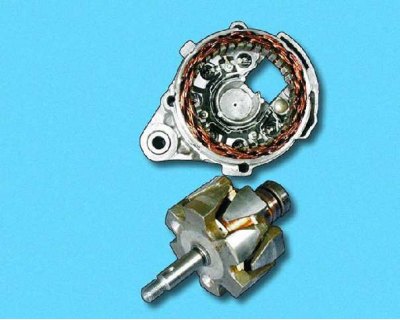
12. Remove the anchor from the manifold side cover.
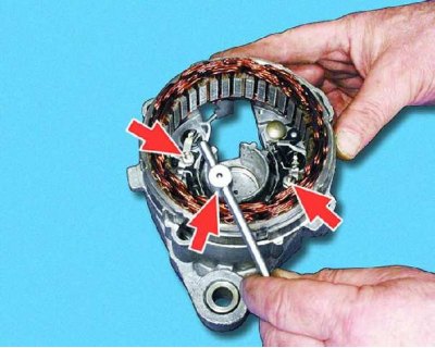
13. Unscrew the three fastening nuts and disconnect the stator terminals from the rectifier unit.
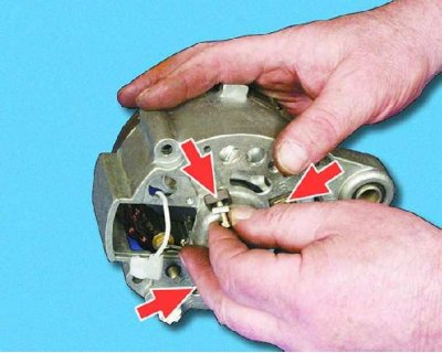
14. Remove the three bolts securing the rectifier block and the stator terminals with insulating pads.
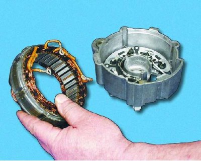
15. Remove the stator from the cover.
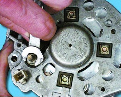
16. Unscrew the terminal "30" fastening nut.
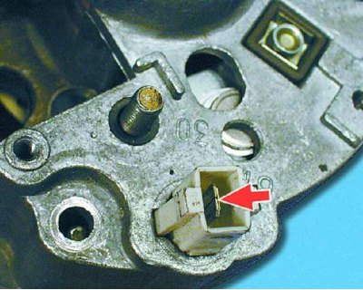
17. Press the lug on the plug inside the block with a screwdriver and push the plug with the wire inside the cover. The plastic block remains on the cover.
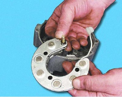
18. Remove the rectifier unit from the cover.
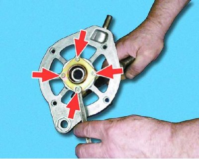
19. To replace the bearing in the drive side cover, unscrew the four mounting nuts, remove the bolts and...
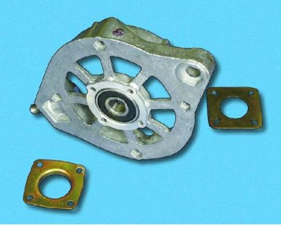
20....remove the inner and outer bearing mounting washers. Then, using a suitable mandrel, press the bearing out of the cover. Press the new bearing flush with the cover surface. Apply force only to the outer bearing ring.
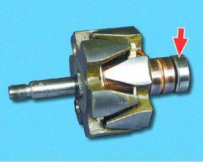
21. To replace the bearing on the commutator side, press it off the armature shaft with a puller. Press the new bearing until it stops, applying force only to the inner bearing race.
Defect detection
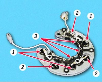
Rectifier block: 1 - positive diodes; 2 - negative diodes; 3 – additional diodes
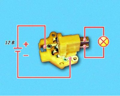
22. Check the voltage regulator for proper operation. Connect a 12 V test lamp to the brushes. Apply 12 V: "+" to the terminal and "-" to the brush holder "ground". The test lamp should light up.
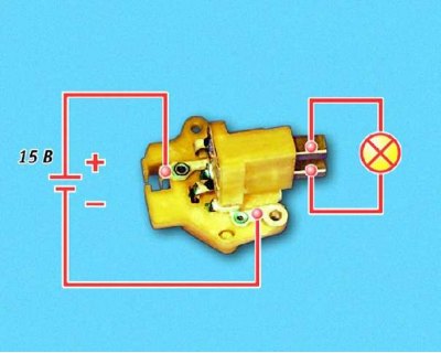
23. Increase the voltage to 15-16 V - the lamp should go out. If the lamp does not go out or does not light at 12 V, replace the regulator with the brush holder.
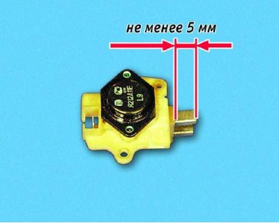
24. Check the ease of movement of the brushes in the brush holder and their protrusion. If the brushes protrude from the brush holder by less than 5 mm, replace the voltage regulator with the brush holder. If chips or cracks are found on the brushes, replace the regulator.
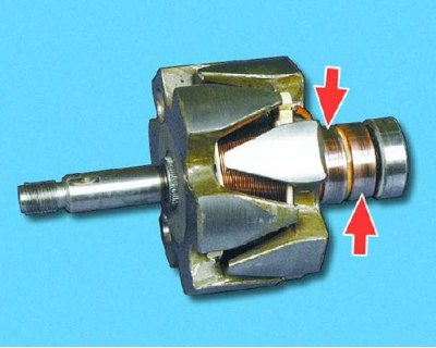
25. Inspect the contact rings. If they have burrs, scratches, marks, wear marks from brushes, etc., the rings must be ground. If the damage to the rings cannot be removed with sandpaper, turn the rings on a lathe, removing a minimum layer of metal, and then grind.
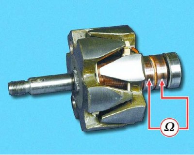
26. Check the rotor winding resistance with an ohmmeter (tester) by connecting it to the contact rings. If the ohmmeter shows "infinity", then there is a break in the windings and the rotor needs to be replaced.
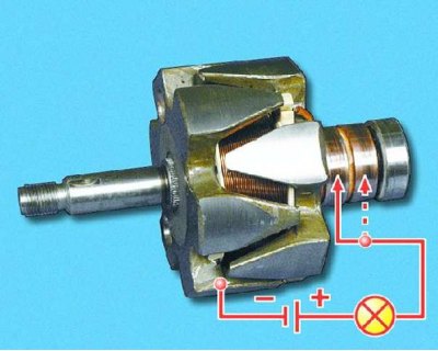
27. Use a test lamp to check if the winding is short-circuited to the rotor housing. Connect the test lamp to the battery. Connect one of the wires to the rotor housing, and the second one to the rings in turn. In both cases, the lamp should not light. If the lamp lights up, the winding is short-circuited: the rotor must be replaced.
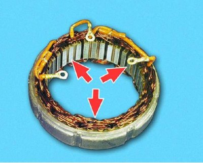
28. Inspect the stator. There should be no traces of the anchor rubbing against the stator on the inner surface of the stator. If there is wear, the bearings or generator covers should be replaced.
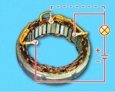
29. Check for a break in the stator winding. Connect the test lamp to the battery. Connect the test lamp to the winding terminals one by one. In all three cases, the lamp should light. If the lamp does not light, there is a break in the winding. Replace the stator or winding.
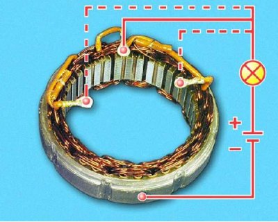
30. Check for a short circuit between the stator windings and the housing. Connect a test lamp to the battery. Connect the lamp to the stator winding terminal and the wire from the power source to the stator housing. If the lamp lights up, there is a short circuit: the stator or winding must be replaced.
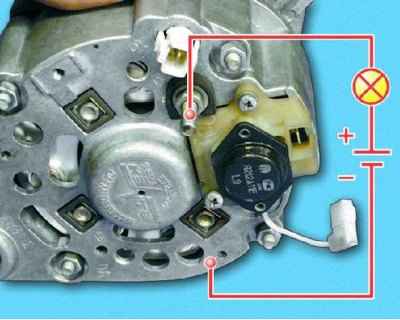
31. Check the rectifier block diodes with a 12 V test lamp and a battery. To check for a short circuit in the positive and negative diodes, connect the "+" of the battery through the test lamp to the "30" terminal of the generator, and the "-" of the battery to the generator body. If the lamp lights up, there is a short circuit in the diodes and the block must be replaced (see recommendation).
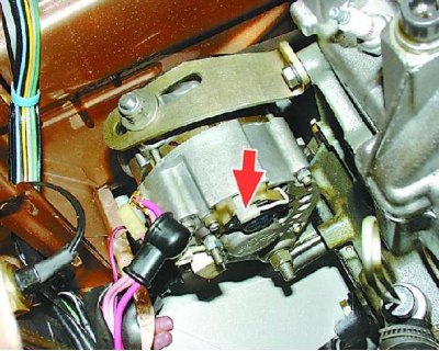
Recommendation for operation 31. You can check the rectifier unit without removing the generator from the car. To do this, disconnect the wires from the battery and generator, and remove the connector with the wire from the voltage regulator terminal.
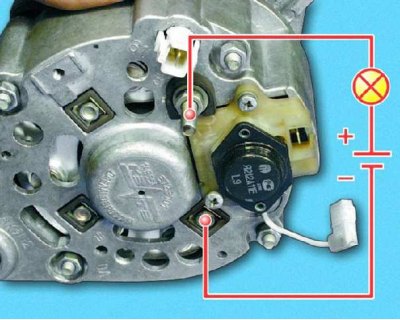
32. To check the positive diodes, connect the "+" of the battery via a test lamp to the "30" terminal of the generator, and the "-" of the battery to one of the rectifier unit mounting bolts. If the lamp lights up, there is a short circuit in the positive diodes: the unit must be replaced.
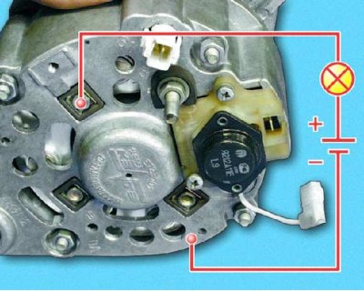
33. To check the negative diodes, connect the "+" of the battery via a test lamp to one of the rectifier unit mounting bolts, and the "-" of the battery to the generator housing. If the lamp lights up, there is a short circuit in the negative diodes: the unit must be replaced (see warning).
Warning for operation 33. A burning lamp when checking negative diodes may also indicate a short circuit of the stator winding to the generator housing, however, such a malfunction occurs much less frequently than a short circuit of the diodes.
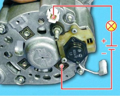
34. To check the additional diodes, connect the "+" of the battery via a test lamp to the "61" terminal of the generator, and the "-" of the battery to one of the rectifier unit mounting bolts. If the lamp lights up, there is a short circuit in the additional diodes. The unit must be replaced.
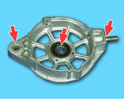
35. Inspect the drive-side alternator cover. If there are cracks, especially where the alternator is mounted, replace the cover. Measure the diameter of the bearing seat in the drive-side cover. If the bearing hole is deformed or its diameter exceeds 42 mm, replace the cover.
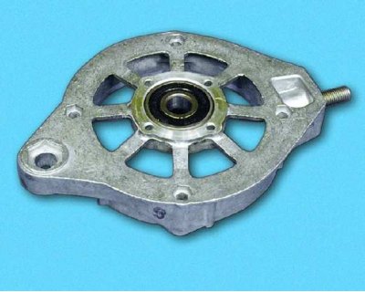
36. Check the ease of rotation of the bearings. If there is play between the rings, rolling or jamming of the rolling elements when the bearings rotate, the bearings must be replaced. Also replace bearings with damaged protective rings or traces of grease leakage.
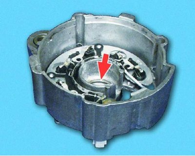
37. Inspect the generator cover from the contact ring side. If there is damage or the bearing seat ring is worn, replace the cover.
The material is posted on the online resource: VAZBOOK.RU
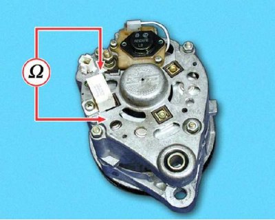
38. The capacitor's serviceability can be checked with a megohmmeter or a tester (on a scale of 1–10 MOhm). Connect one tester probe to the capacitor contact, and the other to the generator body. Before connecting, the device shows "infinity". At the moment of connection, the resistance should decrease and then return to its previous position: in this case, the capacitor is in good condition. A faulty capacitor must be replaced.
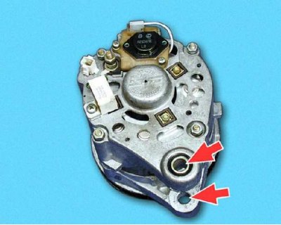
39. Assemble the generator in the reverse order of disassembly. Please note: the holes in the covers for mounting the generator must be aligned (according to the manufacturer's data, the deviation from coaxiality should not exceed 0.4 mm). Tighten the generator pulley mounting nut to a torque of 39–90 Nm (3.9–9.0 kgf/m)