
On fig. 79 shows a diagram of the system for reducing the toxicity of exhaust gases on a vehicle with an optional configuration. The sensor-distributor 19 has an electronic-mechanical device that generates a signal that determines the moment of sparking. This signal controls the switch 16, which interrupts the current in the primary winding of the ignition coil 17, as a result of which a high-voltage pulse is generated in the secondary winding, transmitted through the distributor sensor to the corresponding spark plug.
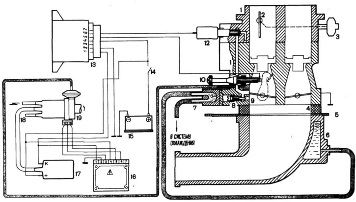
Pic. 79. Scheme of the system for reducing the toxicity of exhaust gases on a car with an optional configuration:
1 - carburetor; 2 - air damper; 3 - starting device; 4 - heat-insulating spacer; 5 - heat shield; 6 - inlet pipe; 7 - heating of the idle system; 8 - mixture quality screw; 9 - throttle actuator lever; 10 - throttle stop screw; 11 - channel of the idle system; 12 - solenoid valve; 13 - control unit; 14 - ignition switch; 15 - battery; 16 - electronic switch; 17 - ignition coil; 18 - high-voltage wires; 19 - sensor-distributor.
Due to the fact that the BSZ is a high energy ignition system, it is not allowed to start the engine using a spark gap, and with the engine running, disconnect the high voltage wires and check the high voltage circuits for «spark», as this can lead to burnout of high-voltage parts and failure of the ignition system.
Spark plugs used in BSZ, A17DV-10 with a gap between the electrodes of 0.7-0.8 mm. The frequency of changing spark plugs is every 20,000 km.
The carburetor, unlike that described in the manual, has:
- idle system with solenoid valve 12, heating unit 7 and double float chamber;
- mechanical drive throttle valves with their sequential opening;
- economizer of power modes;
- idle contact on screw 10 for adjusting the amount of mixture.
In the system for reducing the toxicity of exhaust gases, the electronic control unit 13 for the forced idle economizer control (EPHH) through the solenoid valve 12 turns off the idle system at forced idle (engine braking mode), excluding carbon emissions. For carburetor maintenance:
1. The fuel level in the carburetor is checked only at a service station by measuring the size «A» (pic. 80), which should be 2±1 mm. The gap is adjusted by bending the tongue 2.
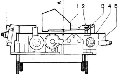
Pic. 80. Setting the fuel level in the carburetor:
1 - float; 2 - tongue; 3 - needle valve; 4 - gasket; 5 - carburetor cover.
2. The frequency of rotation of the crankshaft at idle 750-800 min-1 can be independently adjusted only by screw 1 (pic. 81) the amount of the mixture. Screw 2 of the mixture quality with exhaust gas toxicity control, the carburetor is adjusted only at a service station. For this purpose, screw 2 is closed with a plastic plug. In case of violation or absence of this plug, the plant is not responsible for excessive fuel consumption and increased CO content in the exhaust gases.
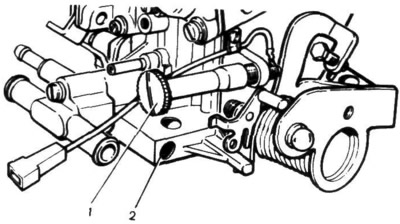
Pic. 81. Carburetor adjusting screws:
1 - mixture quantity screw; 2 - mixture quality screw.
If there is no handle 33 on the instrument panel (rice. 4) carburetor air damper control, the carburetor has a semi-automatic start and engine warm-up. In this case, before starting the engine, press the accelerator pedal and release it, then turn on the starter without pressing the accelerator pedal when starting.
In a variant version, a fine fuel filter is installed in the fuel supply system in front of the fuel pump in the section of the fuel supply line. The filter change interval is 20,000 km. Install the new filter so that the arrow on its housing is directed towards the fuel pump.