




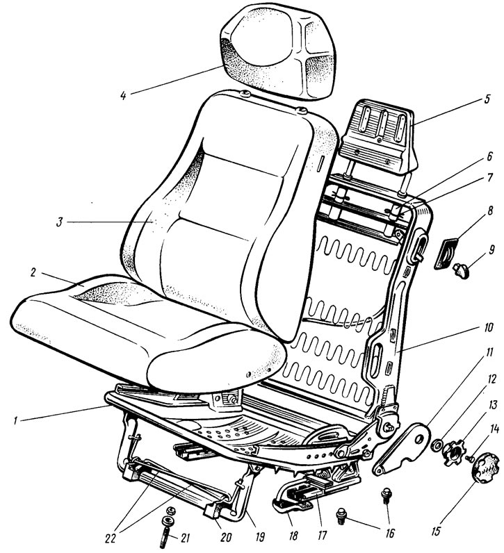
Figure 167. Front seat: 1 - pillow base; 2 - pillow; 3 - back; 4 - headrest; 5 - headrest frame; 6 - headrest guide; 7 - cotter pin; 8 - backrest folding lever trim; 9 - handle of the backrest reclining mechanism; 10 - base of the back; 11 - backrest tilt adjustment mechanism lining; 12 - gasket; 13 - holder of the handle of the backrest tilt adjustment mechanism; 14 - holder mounting bolt; 15 - handle of the backrest tilt adjustment mechanism; 16 - runner mounting bolts; 17 - slide guide, 18 - travel mechanism handle; 19 - base stand; 20 - front bracket; 21 - bracket mounting stud; 22 - torsion bars
Each front seat is mounted on two skids and a rocker post 19 (figure 167), which are attached to the body brackets and to the floor. The stand has two torsion bars 22, facilitating the forward movement of the seat. The working stroke of the seat forward and backward is 119 mm.
The base 1 of the seat cushion is stamped from sheet steel with a thickness of 0.9 mm. The base 10 of the backrest is made of strong steel frames to which wire springs are attached. To avoid creaking, the ends of the springs are covered with a layer of polyamide resin. The bases of the backrest and cushion are connected to each other by a hinge. Soft padding made of polyurethane foam is placed on the bases of the backrest and cushion and covered with upholstery. The headrest 5, adjustable in height, is installed in the guides 6.
Guides 12 (figure 168) and sliders 2 and 10 of the runners are stamped from sheet steel. The movement of each slider along the guide is carried out on two rollers 11. The seat is fixed in the desired position by latches 5, each of which is pressed by spring 4 into one of the grooves of the comb lock 1 of the travel mechanism. The latches are welded to the guides. The levers 6 of the latches of the inner and outer runners are connected to each other by rod 8. Rod 13 of the latch of the outer runners has a handle of the travel mechanism.
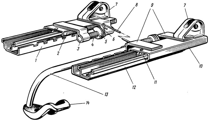
Figure 168. Front seat runners: 1 - lock of the internal slide movement mechanism; 2, 10 - sliders; 3 - internal slide latch axis; 4 - latch spring; 5 - latch of internal slides; 6 - Latch lever; 7 - staples; 8 - latch rod; 9 - outer runner latch brackets; 11 - roller; 12 - outer slide guide; 13 - rod of the handle of the movement mechanism; 14 - handle of the movement mechanism
The mechanism for adjusting the backrest tilt consists of two eccentrics that are turned by a handle. The eccentrics are connected to each other by a synchronizer 9 (figure 169). By turning the eccentrics by the adjustment handle, the toothed pairs of the internal engagement of the upper 4 and lower 3 links turn the upper links. The latter are welded to the base of the backrest and when turned, they change the position of the seat backrest.
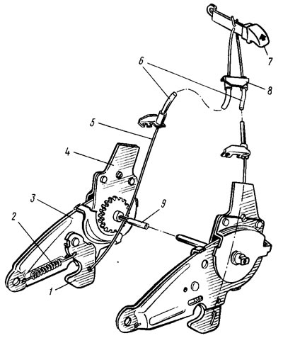
Figure 169. Mechanisms for adjusting the tilt and recline of the front seat back: 1 - hook; 2 - hook spring; 3 - lower link of the backrest tilt adjustment mechanism; 4 - upper link of the backrest tilt adjustment mechanism; 5 - backrest folding mechanism rod; 6 - traction shells; 7 - handle of the backrest folding mechanism lever; 8 - bracket; 9 - synchronizer
To seat passengers in the back seat, the backs of the front seats are folded forward, for which purpose the lower links 3 are installed pivotally on the bases of the cushions. In the normal position, the lower links are fixed by hooks 1 under the action of springs 2. When the handle 7 of the folding mechanism is moved upward, the rods 5 move the hooks back and release the lower links, after which it is possible to move the seat back forward.
[The original can be found on the website VAZbook.ru]