




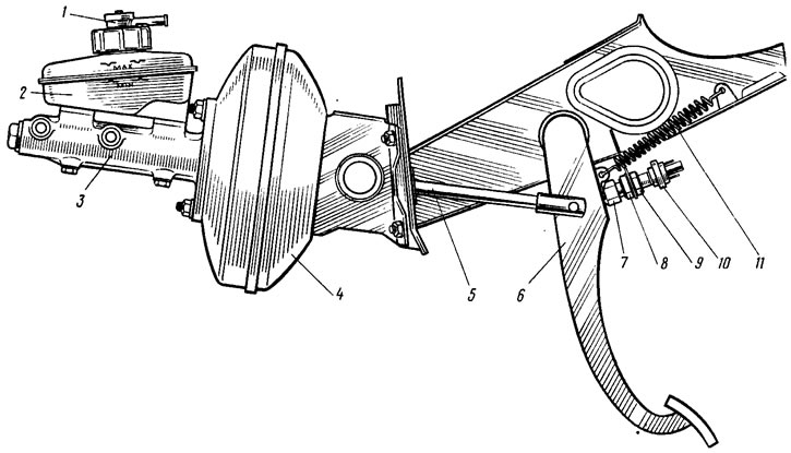
Figure 113. Brake pedal with vacuum booster and master cylinder: 1 - liquid level alarm sensor; 2 - tank; 3 - master cylinder; 4 - vacuum booster; 5 - pusher; 6 - brake pedal; 7 - brake light switch buffer; 8, 9 - brake light mounting nuts; 10 - brake light switch; 11 - pedal return spring
If the brake light switch is too close to the pedal, it will not return to its original position. Valve 18 (see figure 105), pressing against the body 21, separates cavities A and B, and incomplete release of the wheels occurs when the pedal is released. If moving the brake light switch does not eliminate the incomplete release of the brake mechanisms, then disconnect the brake master cylinder from the vacuum booster and check the protrusion of the adjusting screw 4 relative to the plane of the master cylinder flange attachment (size 1.25 mm). This size is set by holding the end of the rod with a special key and tightening or loosening screw 4 with another key.