
English Русский
Български
Беларускі
Український
Српски
Hrvatski
Română
Polski
Slovenský
Magyar
| Articles | Contacts | Sitemap |   
Repair and maintenance Lada Repair and maintenance Mazda Repair and maintenance Mitsubishi Repair and maintenance Toyota Repair and maintenance Land Rover Repair and maintenance Hyundai Repair and maintenance Nissan
VAZbook.ru


Main     1111   2101   2105   2106   2107   2109   2110   2115   2121  
VAZ-2101 (1970-1983) VAZ-21011 (1974-1983)
  • Main
  • «Zhiguli»
  • VAZ-2101
  • Chassis
  • Brake system
  • Adjusting the free travel of the brake pedal, bleeding air from the hydraulic drive

Adjusting the free travel of the brake pedal, bleeding air from the hydraulic drive (VAZ-2101)

            0

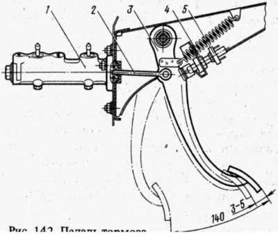
The free travel of pedal 3 (Fig. 142) should be 3-5 mm, and the full travel should be about 140 mm. The free travel is adjusted by moving the brake light switch 5 and then tightening the nut 4. With normal free travel of the pedal, the pusher 2 slightly touches the piston of the master cylinder. The full travel is not adjusted, it is provided by the design of the brake drive.

The free travel of pedal 3 (Fig. 142) should be 3-5 mm, and the full travel should be about 140 mm.…


Air that gets into the brake hydraulic system when replacing pipes, hoses, sealing rings, or when the system is leaking causes an increase in the working stroke of the brake pedal, its "softness", and significantly reduces the effectiveness of the brakes.

Before removing air from the brake system, make sure that all brake drive units and their connections are tight, check and, if necessary, fill the reservoir to the normal level with Neva or Tom liquid. Then thoroughly clean the air removal nipples from dirt and dust and remove the protective caps from them.

Air is removed first from one circuit, then from the other, each time starting from the wheel furthest from the main cylinder. Bleeding of the hydraulic drive is carried out in the following order:


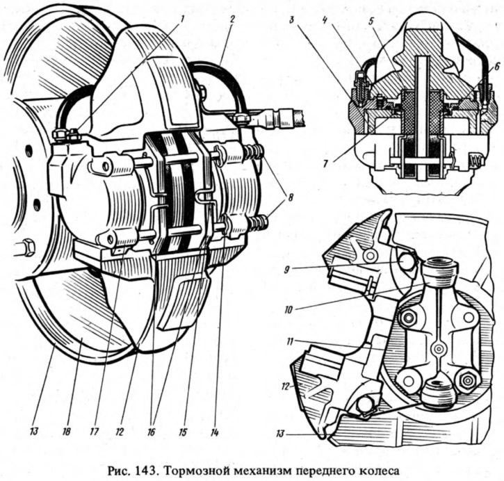
  • remove the front wheels; a rubber hose is placed on the head of the fitting 1 (Fig. 143), and the other end of the hose is lowered into a transparent container partially filled with brake fluid;
  • sharply pressing the brake pedal 3-5 times with intervals of 2-3 seconds between presses, unscrew the nipple 1 by 1/2-3/4 of a turn with the pedal pressed. Continuing to press the pedal, displace the liquid in the system together with the air through the hose into the vessel;
  • its forward position and the flow of liquid through the hose stops, tighten the air release nipple until it stops. These operations are repeated until bubbles stop coming out of the hose;
  • holding the pedal in the pressed position, tighten the nipple until it stops and remove the hose, wipe the nipple dry and put on the protective cap;
  • repeat the operations for the other wheels, first on the second wheel of the same circuit, and then sequentially on both wheels of the second circuit.
repeat the operations for the other wheels, first on the second wheel of the same circuit, and then…


When removing air, maintain a normal fluid level in the brake hydraulic drive reservoir. After completely removing air, the brake pedal should not move more than 1/2-3/4 of its travel.


To eliminate the influence of the pressure regulator on bleeding the brakes, air is removed with the rear wheels loaded (hanging the rear of the vehicle is not allowed).

If the liquid has been drained completely, then before removing air from the system:
  • unscrew the fittings on the cylinders of all wheels by 1.5-2 turns;
  • sharply pressing the brake pedal and slowly releasing it, tighten the nipples as the liquid flows out of them. Then bleed the drive as described above.

If, even after prolonged removal, air continues to come out of the hose in the form of bubbles, it means that it enters the system through damage in the pipelines, due to insufficient tightness of the connections, or as a result of a malfunction of the main or wheel cylinders.

If air removal is performed on a vehicle whose brake system has been in operation for a long time, the fluid in the system is replaced with new fluid.

[The original is on the portal www.VAZbook.ru]


This article is available at russian, bulgarian, belarusian, ukrainian, serbian, croatian, romanian, polish, slovak, hungarian
The text was reviewed by the specialist: Grigory Vologodtsev

Share with friends:

Previous articles
VAZ-2101: Brake system
Next articles

Disassembly, inspection of parts and assembly of the pressure regulator
Removal and installation the pressure regulator
Checking the performance of the pressure regulator
The design and operation of the brake pressure regulator
Checking and repairing the brake pedal assembly
The design and operation of the front wheel brakes
Removal and installation front wheel brakes
Disassembly, inspection of parts and assembly of front wheel brakes
The structure and operation of the rear wheel brakes
Disassembly, assembly and installation of rear wheel brakes

More articles from other manuals on VAZ cars:
➠ Adjusting the brake pedal free travel VAZ-1111 (1988-1996)
➠ Adjusting the brake pedal free travel VAZ-2109 (1984-1997)
➠ Removal the brake booster and adjusting the brake pedal free… VAZ-21214 (1994-2006)
➠ Adjusting and bleeding the clutch hydraulic drive VAZ-2105 (1979-2010)
➠ Hydraulic brake drive — bleeding and replacing brake fluid VAZ-2106 (1976-2006)
Link in different formats to this page


Visitor comments

No comments yet


How much will 31 + 11 ?


VAZ-2101 (1970-1983) 
  • General information
  • Vehicle description
  • Vehicle device
  • Vehicle operation
  • Maintenance
  • Main malfunctions
  • Applications
  • Power unit
  • Engine repair
  • Cooling and lubrication system
  • Supply system
  • Transmission
  • Clutch
  • Transmission
  • Cardan gear
  • Rear axle
  • Chassis
  • Front suspension
  • Rear suspension
  • Steering
  • Brake system
  • Body
  • Exterior
  • Interior
  • Electrical equipment
  • Engine electrics
  • Equipment and devices


VAZ-21011 (1974-1983) 
  • General information
  • Specifications
  • Operation and maintenance
  • Power unit
  • Engine repair
  • Cooling system
  • Lubrication system
  • Power and exhaust system
  • Ignition system
  • Engine electrics
  • Transmission
  • Clutch
  • Car gearbox
  • Cardan gear
  • Rear axle
  • Chassis
  • Car suspension
  • Steering
  • Brake system
  • Body
  • Exterior
  • Interior
  • Doors and locks
  • Electrical equipment
  • Equipment and devices
  • Lighting and signaling


VAZbook.ru © 2017 · Mobile version · Contact with administration · Sitemap: EN BG BY UA RS HR RO PL SK HU · Site search · News and articles VAZ-1111 · VAZ-11113 · VAZ-2101 · VAZ-21011 · VAZ-2104 · VAZ-2105 · VAZ-21051 · VAZ-2106 · VAZ-21061 · VAZ-2107 · VAZ-21099 · VAZ-2109 · VAZ-2108 · VAZ-2110 · VAZ-2112 · VAZ-2114 · VAZ-2115 · VAZ-2121 · VAZ-21213 · VAZ-21214 ·
The site stores technical data using cookies to improve the service.