
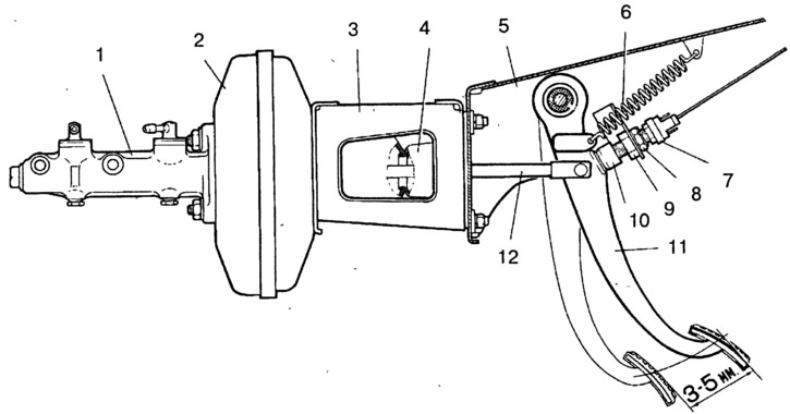
Pic. 6-3. Brake pedal:
1 - main cylinder; 2 - vacuum amplifier; 3 - vacuum booster bracket; 4 - a glass of a sealant; 5 - bracket for fastening the clutch and brake pedals; 6 - retraction spring of the brake pedal; 7 - stoplight switch; 8, 9 - nuts; 10 - brake light switch buffer; 11 - brake pedal; 12 - pusher.
If the brake light switch is too close to the pedal, then it does not return to its original position, valve 18 (rice. 6-2), pressing against the body 21, separates the cavities A and B, and there is an incomplete release of the wheels when the pedal is released.
The position of the brake light switch is regulated by its movement with the nut released 8 (pic. 6-3). Install it so that the brake light switch buffer lightly touches the pedal stop, while the free play of the pedal should be 3-5 mm. After adjustment, tighten nut 8.
Warning: Adjust the brake pedal free play with the engine off.
If by moving the brake light switch it is not possible to eliminate the brake release, then disconnect the brake master cylinder from the vacuum booster and check the protrusion of the adjusting bolt 4 (rice. 6-2) relative to the mounting plane of the master cylinder flange (size 1.25-0,2). This dimension can be set by holding the end of the stem 1 with a special key, and turning or unscrewing the bolt 4 with another key.