
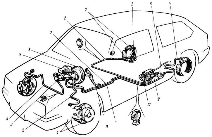
Pic. 104. Scheme of hydraulic brakes: 1 - brake mechanism of the front wheel; 2 - circuit pipeline «left front - right rear brakes»; 3 - the main cylinder of the hydraulic drive of the brakes; 4 - circuit pipeline «right front - left rear brakes»; 5 - tank of the main cylinder; 6 - vacuum amplifier; 7- brake mechanism of the rear wheel; 8 - elastic lever drive pressure regulator; 9 - pressure regulator; 10 - pressure regulator drive lever; 11 - brake pedal
The car is equipped with working and parking brake systems. The service brake system consists of four brake mechanisms and a hydraulic drive, which has a diagonal separation of circuits (pic. 104). One hydraulic drive circuit ensures the operation of the right front and left rear brake mechanisms, the other - the left front and right rear. This greatly improves driving safety.
The hydraulic drive includes a vacuum booster 6 and a double-circuit regulator 9 of the pressure of the rear brakes.
The first reduces the force on the brake pedal, the second increases the safety of the car. In addition to the hydraulic drive, the rear wheel brakes are mechanically driven by a parking brake lever mounted on the floor of the body.
Vacuum booster
Rubber diaphragm 10 (pic. 105) together with the valve body 21, the cavity of the vacuum booster is divided into two chambers: vacuum A and atmospheric B. Chamber A is connected to the engine intake pipe.
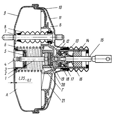
Pic. 105. Vacuum booster: 1 - stock; 2 - sealing ring of the flange of the main cylinder, 3 - cup of the amplifier housing; 4 - adjusting screw; 5 stem seal; 6 - diaphragm return spring; 7 - amplifier pin; 8 - sealing case; 9 - amplifier housing, 10 - diaphragm; 11 - amplifier housing cover; 12 - piston; 13 - protective cover of the valve body; 14 - air filter; 15 - pusher; 16 - pusher return spring; 17- valve spring; 18 - valve; 19 - valve body bushing; 20 - stock buffer; 21 - valve body; A - vacuum chamber; B - atmospheric chamber; V, G - channels
The valve body 21 is plastic. At the exit from the cover, it is sealed with a corrugated protective cover 13. In the valve body there is a rod 1 of the main cylinder drive with a support sleeve, a rod buffer 20, a piston 12 of the valve body, a valve 18 assembly, return springs 16 and 17 of the pusher and valve, an air filter 14 pusher 15.
When the pedal is pressed, the pusher 15 moves, the piston 12 and the valve body 21, and after them the valve 18 until it settles into the seat of the valve body. At, the chamber atom A and B are separated. With further movement of the piston, its seat moves away from the valve and through the resulting gap, chamber B is connected to the atmosphere. The air that enters through the filter 14, the gap between the piston and the valve and channel B, presses on the diaphragm 10. Due to the pressure difference in chambers A and B, the valve body is mixed together with the stem 1, which acts on the master cylinder piston. When the pedal is released, the valve moves away from its body and through the resulting gap and channels C and D, chambers A and B communicate with each other. Pressure regulator. This device regulates the pressure in the hydraulic drive of the rear wheel brakes depending on the load on the rear axle of the car (pic. 106). It is included in both circuits of the brake system, and through it the brake fluid flows to both rear brake mechanisms.
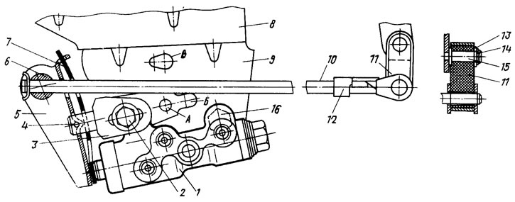
Pic. 106. Pressure regulator drive
The pressure regulator 1 is attached to the bracket 9 with two bolts 2 and 16. In this case, the front bolt 2 simultaneously fastens the fork bracket 3 of the lever 5 of the pressure regulator drive. On the pin of this lever, a two-arm lever 5 is hinged with a pin 4. Its upper arm through the axis 6 is connected to the elastic lever 10, the other end of which is pivotally connected through the earring 11 to the rear suspension arm bracket. The bracket 3 together with the lever 5 can be moved relative to the pressure regulator due to the oval holes for the fastening bolt. This regulates the force with which lever 5 acts on the regulator piston (see sect. «Pressure Regulator Actuator Adjustment»).
The regulator has four chambers: A and D (pic. 107) connected to the master cylinder. B - with the right, and C - with the left wheel cylinders of the rear brakes.
Pic. 107. Pressure regulator
In the initial position of the brake pedal, piston 2 is pressed by lever 5 (see fig. 106) through the leaf spring 7 to the pusher 20 (see fig. 107), which under this force is pressed against the seat 14 of the valve 18. In this case, the valve 18 is pressed from the seat and a gap I is formed, as well as a gap K between the piston head and the seal 21. Through these gaps, the chambers A and D communicate with the chambers B and C.
When you press the brake pedal, the fluid through the gaps K and I and chambers G and C enters the wheel cylinders of the brake mechanisms. With an increase in fluid pressure, the force on the piston increases, tending to push it out of the housing. When the force from the pressure exceeds the force from the elastic lever, the piston begins to move out of the body, and after it the pusher 20 moves under the action of the springs 12 and 17 together with the sleeve 19 and rings 10. In this case, the gap increases, and the gaps I and K decrease. When gap And is completely selected and valve 18 isolates chamber G from chamber B, pusher 20, together with the parts located on it, stops moving after the piston. Now the pressure in chamber C will vary depending on the pressure in chamber B. With a further increase in the effort on the brake pedal, the pressure in chambers A and A increases, piston 2 continues to move out of the housing, and sleeve 19, together with sealing colts 10 and plate 11, under the reinforcing pressure in chamber B shifts towards plug 16. At the same time, gap G begins to decrease. By reducing the volume of chamber B, the pressure in it, and hence in the brake drive, will increase and will practically be equal to the pressure in chamber B. When gap A is completely selected, the pressure in chamber B. and hence in chamber C, will increase in less than the pressure in chamber A due to the throttling of fluid between the piston head and seal 21. The relationship between the pressure in chambers B and A is determined by the ratio of the difference between the areas of the head and piston rod to the area of the head.
A hole is made in the body of the regulator, closed by a plug 24. The leakage of liquid from under the plug when it is squeezed out indicates leaks in the elbows 10.
Master cylinder
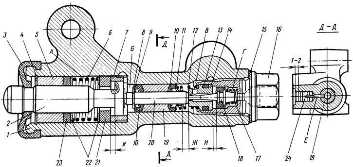
Tank 13 is attached to the main cylinder body (pic. 108), in the filler neck of which the sensor 14 of the emergency level of the brake fluid is installed. O-rings 5 high pressure are used from the rear wheel cylinder.
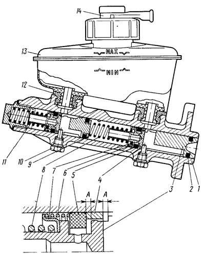
Pic. 108. The main brake cylinder: 1 - body; 2 - sealing ring; 3 - circuit drive piston «left front - right rear brakes»; 4 - spacer ring; 5 - high pressure sealing ring; 6 - clamping spring of the sealing ring; 7 - spring plate; 8 - piston return spring; 9 - washer; 10 - locking screw; 11 - circuit drive piston «right front - left rear brakes»; 12 connecting sleeve; 13 - tank; 14 - emergency liquid level sensor; A - compensation gaps
Front wheel brake
Disc with automatic adjustment of the gap between the pads and the disc, with a floating bracket. The bracket is formed by a caliper 3 (pic. 109) and wheel cylinder 5, which are tightened with bolts. The movable bracket is bolted to the guide pins 9. which are installed in the holes of the guide 2 of the blocks. These holes are filled with grease. Rubber covers 8 are installed between the fingers and the guide pads. Brake pads 4 are pressed against the grooves of the guide by springs. A piston 6 with a sealing ring 7 is installed in the cavity of the wheel cylinder. Due to the elasticity of this ring, an optimal gap is maintained between the pads and disk 1, the surface of which is protected by casing 10.
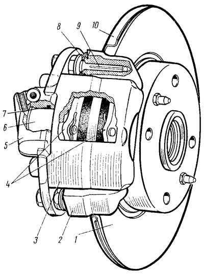
Pic. 109. Front wheel brake
When braking under fluid pressure, the piston 6 presses the inner pad against the disc, after which the reaction force moves the movable bracket on the fingers 9 and the outer pad is also pressed against the disc. In this case, the pressing force of the pads will be the same. When releasing due to the elasticity of the sealing ring 7, the piston is retracted from the pad and a small gap is formed between the pads and the disc.
Rear wheel brake
Drum, with automatic adjustment of the gap between the shoes and the drum (pic. 110). The automatic clearance adjustment device is located in the wheel cylinder 3 (pic. 111). Its main element is a split thrust ring 9, mounted on the piston 4 between the shoulder of the thrust screw 10 and two crackers 8 with a gap of 1.25-1.65 mm. Thrust rings 9 are installed in the cylinder with an interference fit, providing a shear force of the ring along the cylinder mirror of at least 35 kgf, which exceeds the force on the piston from the coupling springs 3 and 7 (see fig. 110) brake pads. When the pads are worn, the gap of 1.25-1.65 mm is completely eliminated, the collar on the stop screw is 10 (see fig. 111) is pressed against the shoulder of the ring 9. As a result, the thrust ring, under the pressure of the brake fluid, moves after the piston by the amount of wear. With the cessation of braking, the pistons are shifted by the force of the coupling springs until the crackers stop against the collar of the thrust ring. This maintains the optimal clearance between the pads and the drum.
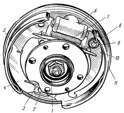
Pic. 110. Rear wheel brake: 1 - civiihum fastening nut; 2 - wheel hub; 3 - lower coupling spring of the shoes; 4 - brake shoe; 5 - guide spring; 6 - wheel cylinder; 7 - upper coupling spring; 8 - expanding bar; 9 - finger of the parking brake lever; 10 - parking brake drive lever; 11 - brake shield
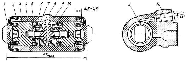
Pic. 111. Wheel cylinder
Stops 1 of the pads are pressed into the pistons, and fitting 11 is screwed into the cylinder for bleeding the brake.
Parking brake
Has a mechanical drive. acts on the brake mechanisms of the rear wheels. It consists of lever 1 (pic. 112), adjusting rod 5, equalizer c, cable 10. lever 13 of the manual drive of the shoes and expansion bar 15. Relevant parts (10—14) installed in the right wheel brake drive.
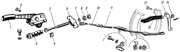
Pic. 112. Parking brake parts
Possible malfunctions of the brake system, their causes and methods of elimination are given in tab. 15.