




Contents: Disassembling the outer hinge ↓ Assembling the outer hinge ↓ Disassembling the inner hinge ↓ Assembly of the inner hinge ↓
Disassembling the outer hinge
The joint is disassembled only if the protective cover 8 is damaged (see figure 76), when there is a need to replace the lubricant.
To disassemble the outer joint, use tool 67.7814.9508 to remove clamps 5 and 9 and move protective cover 8 along the wheel drive shaft (the right wheel drive cover is pressed or unscrewed).
Using a punch and a hammer, knock the hinge off the shaft, applying force to the collar 3. Then wash the hinge.
Before disassembling, mark the relative position of the clip 3 with paint or a whetstone (figure 77), separator 2 and the hinge housing 1. Secure the outer hinge in a vice as shown in Figure 78. Tilt the collar and separator so that one ball comes out of the hinge housing groove as completely as possible. Use a screwdriver made of a soft material to push the ball out of the separator. Then turn all the parts so that the adjacent ball takes the same position and remove it from the separator.
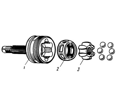
Figure 77.. External hinge parts |
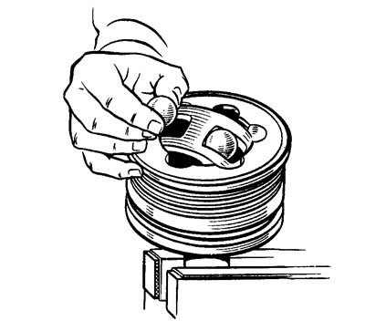
Figure 78. Removing balls from the separator |
Using the above techniques, remove the remaining balls.
The sequence of removing the balls may be different - through one ball. Light tapping on the separator or the cage with an object made of soft material is allowed. Excessive force of turning the separator is unacceptable, as it may block the balls, which will complicate further disassembly.
The separator with the collar is installed so that the elongated windows of the separator (are marked with arrows in Figure 79) are positioned against the projections of the hinge housing and the separator is removed together with the collar. The collar is removed from the separator, for which one of the collar projections is placed in the elongated window of the separator (figure 80) and roll out the cage. Once again, thoroughly wash the hinge parts and check the condition of all parts, paying special attention not only to their wear and damage, but also to the presence of corrosion. If the wear of the working surfaces is more than 0.1 mm, or there is damage or corrosion, replace the hinge assembly.
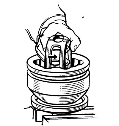
Figure 79. Removing the separator assembly with the collar from the hinge housing |
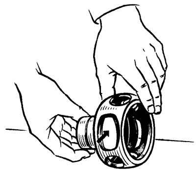
Figure 80. Removing the clip from the separator |
Assembling the outer hinge
The outer joint is assembled in the reverse order of disassembly, taking into account the following:
- before assembly, all parts are greased with SHRUS-4 grease;
- when installing the separator assembly with the collar into the hinge housing, it is necessary to ensure that the marks applied before disassembly match;
- when installing balls in the separator, tilt the cage at an angle approximately 2 times greater than the separator;
- fill the joint with SHRUS-4 grease in the amount of 40 cm³;
- install a new retaining ring in the shaft groove strictly in its center, using consistent grease. Then rest the shaft against the collar so that the ring remains aligned with the shaft and the collar. Sharply hit the end of the wheel drive shaft. In this case, the retaining ring is compressed and slides through the opening in the collar;
- before installing the inner clamp, release the air from the cover, for which purpose pull the seat belt of the cover away from the drive shaft with a screwdriver, check for cracks and deformations in the area of the clamp sockets. If any are found, replace the clamps with new ones using device 67.7814.9508;
- when installing the clamp lock, the top of the locking tooth is positioned in the direction of rotation of the hinge.
Disassembling the inner hinge
Disassembly sequence:
- remove clamps 5 and 9 (see figure 76) with device 67.7814.9508 and slide the protective cover 8 along the shaft (the right wheel drive cover is pressed or unscrewed);
- apply marks to indicate the relative positions of the parts to be separated;
- remove the retainer 11 from the hinge housing, and then the shaft 10 assembled with the collar 3, separator 6 and balls 4;
- using a soft screwdriver, remove the balls and take the cage out of the separator;
- using the above techniques (see "Disassembling the outer hinge"), separate the hinge parts, wash them and carefully check the condition of all the parts. If the working surfaces are worn more than 0.1 mm, or if the parts are damaged or corroded, replace the hinge assembly.
Assembly of the inner hinge
The internal joint is assembled in the reverse order of disassembly. In this case, before installing the collar on the shaft splines, make sure that the collar's annular groove for the thrust ring is installed towards the shaft. After assembly, make sure that the collar assembly with the separator and balls moves freely along the entire length of the housing grooves under the force of the hand. Otherwise, identify the cause of jamming and, if parts are damaged, replace the joint as an assembly. Then, having made sure of the correct assembly, put 80 cm³ of SHRUS-4 grease into the joint.
Before installing the clamps, release the "excess" air from the boot by pulling the boot seat belt away from the drive shaft with a screwdriver.