
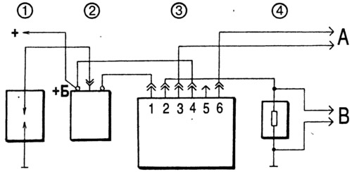
Pic. 7-25. Scheme for checking the switch:
1 - arrester; 2 - ignition coil; 3 - switch; 4 - resistor 0.01 Ohm±1%, not less than 20 W; A - to the generator of rectangular pulses; B - to the oscilloscope.
On terminals «3» and «6» The commutator receives square-wave pulses imitating sensor pulses. The pulse frequency is from 3.33 to 233 Hz, and the duty cycle (ratio of period to pulse duration t/tAnd) equal to 3. Maximum voltage Umax - 10 V, and the minimum Umin - no more than 0.4 V (pic. 7-26 II). For a working switch, the shape of the current pulses must correspond to the oscillogram I.
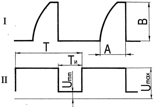
Pic. 7-26. The shape of the pulses on the oscilloscope screen:
I - commutator impulses; II - generator pulses; A - current accumulation time; B is the maximum current value; T - pulse period; TAnd - pulse duration.
For switches 3620.3734 and 76.3734 at supply voltage (13,5±0,5) In the magnitude of the current (IN) should be 7.5-8.5 A. Current accumulation time (A) not standardized.
For RT1903 switch with supply voltage (13,5±0,2) At and a pulse frequency of 25 Hz, the current strength is 7-8 A, and the current accumulation time is 5.5-11.5 ms.
For switch PZE4022 with supply voltage (14±0,3) At a frequency of 25 Hz, the current strength is 7.3-7.7 A, and the current accumulation time is not standardized.
For K563.3747 switch with supply voltage (13,5±0,5) At a frequency of 33.3 Hz, the current strength is 7.3-7.7 A, and the current accumulation time is not standardized.
If the shape of the commutator pulses is distorted, then there may be interruptions in sparking or it may occur with a delay. The motor will overheat and not develop its rated power.