English Русский
Български
Беларускі
Український
Српски
Hrvatski
Română
Polski
Slovenský
Magyar
| Articles | Contacts | Sitemap |   
Repair and maintenance Lada Repair and maintenance Mazda Repair and maintenance Mitsubishi Repair and maintenance Toyota Repair and maintenance Land Rover Repair and maintenance Hyundai Repair and maintenance Nissan
VAZbook.ru


Main     1111   2101   2105   2106   2107   2109   2110   2115   2121  
VAZ-2108 (1984-2003) VAZ-2109 (1984-1997) VAZ-21099 (1990-2004)
  • Main
  • «Sputnik»
  • VAZ-21099
  • Power unit
  • Engine repair
  • Disassembling the cylinder head

Disassembling the cylinder head (VAZ-21099)

            0

Disassembling the cylinder head


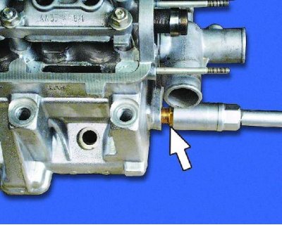
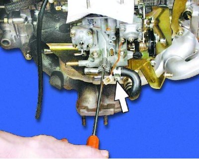
1. Loosen the fastening screw and disconnect the heating nipple from the carburetor. If the screw cannot be loosened, loosen the clamp and remove the hose from the nipple.
1. Loosen the fastening screw and disconnect the heating nipple from the carburetor. If the screw…


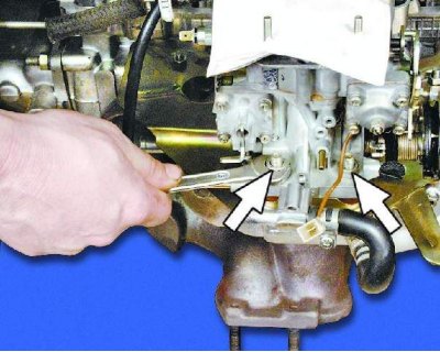
2. Unscrew the four carburetor mounting nuts (two of them are located on the opposite side).
2. Unscrew the four carburetor mounting nuts (two of them are located on the opposite side).


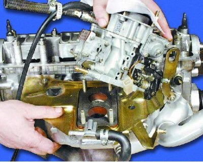
3. Remove the carburetor from the intake manifold.
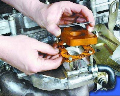


3. Remove the carburetor from the intake manifold.


4. Carefully remove the carburetor gaskets.
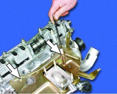
4. Carefully remove the carburetor gaskets.


5. Unscrew the two nuts securing the carburetor heat-insulating shield.
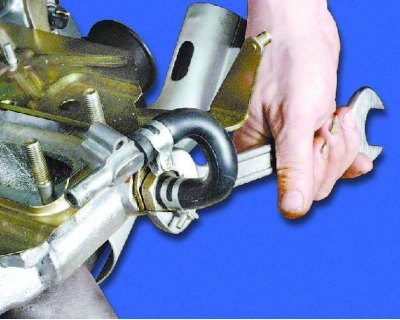
5. Unscrew the two nuts securing the carburetor heat-insulating shield.


6. Loosen the nut on the fitting.
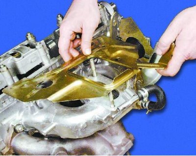
6. Loosen the nut on the fitting.


7. Remove the heat-insulating shield.
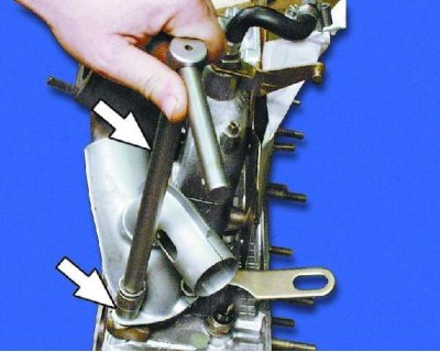

7. Remove the heat-insulating shield.


8. Unscrew the two nuts securing the warm air intake pipe.
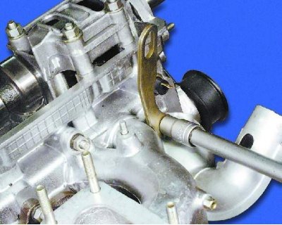
8. Unscrew the two nuts securing the warm air intake pipe.


9. Loosen the eye mounting nut.
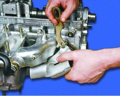
9. Loosen the eye mounting nut.


10. Remove the eye and the warm air intake pipe.
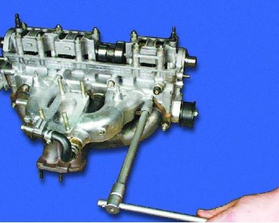
10. Remove the eye and the warm air intake pipe.


11. Remove the nine nuts securing the intake pipe and exhaust manifold.
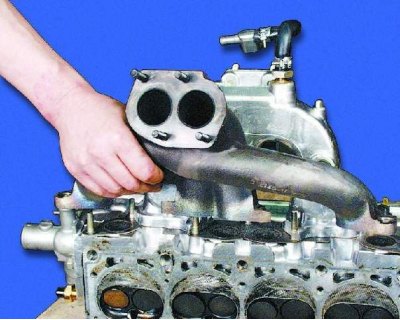
11. Remove the nine nuts securing the intake pipe and exhaust manifold.


12. Remove the exhaust manifold.
12. Remove the exhaust manifold.


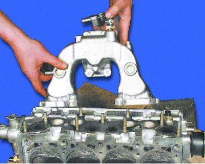
13. Remove the intake pipe.
13. Remove the intake pipe.


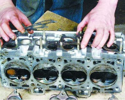
14. Remove two gaskets (see note).
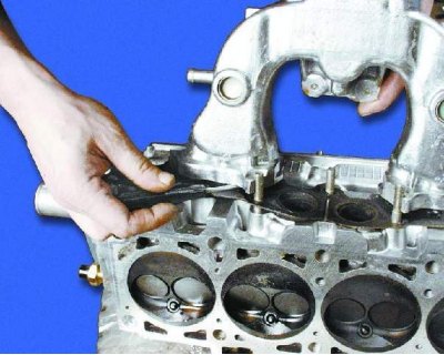
14. Remove two gaskets (see note).


Note: Remove the sealing gaskets carefully. If the gaskets are not damaged and not too compressed, they can be reused. Carefully separate the burnt gaskets with a screwdriver.

Note: Remove the sealing gaskets carefully. If the gaskets are not damaged and not too compressed,…


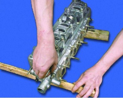
Note: After removing the exhaust manifold and intake pipe, place wooden shims under the cylinder head to avoid damaging the valves protruding from the cylinder head.

Note: After removing the exhaust manifold and intake pipe, place wooden shims under the cylinder…


15. Remove the spark plugs.

15. Remove the spark plugs.


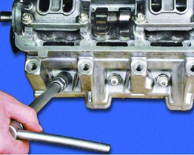
16. Remove the coolant temperature sensor.
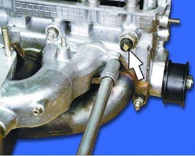
16. Remove the coolant temperature sensor.


17. Unscrew the oil pressure warning light sensor.
17. Unscrew the oil pressure warning light sensor.


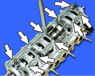
18. Remove the ten nuts securing both camshaft bearing housings.
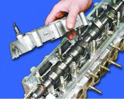
18. Remove the ten nuts securing both camshaft bearing housings.


19. Remove both camshaft bearing housings from the cylinder head.
19. Remove both camshaft bearing housings from the cylinder head.


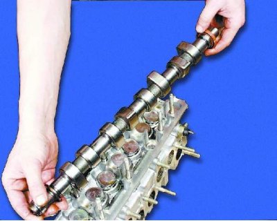
20. Remove the camshaft.
20. Remove the camshaft.


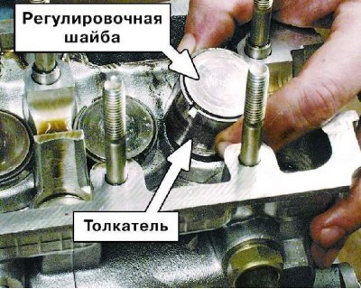
Warning: When removing each tappet, mark it and the adjusting washer with a serial number so that they can be installed in their proper place during assembly.

Warning: When removing each tappet, mark it and the adjusting washer with a serial number so that…


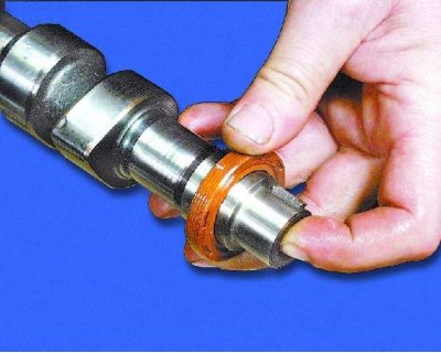
21. Remove the oil seal from the front end of the camshaft.
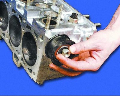
21. Remove the oil seal from the front end of the camshaft.


22. Loosen the tension roller mounting nut.
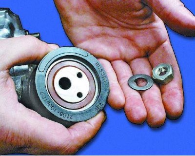
22. Loosen the tension roller mounting nut.


23. Remove the tension roller and the thrust washer installed underneath it.
23. Remove the tension roller and the thrust washer installed underneath it.


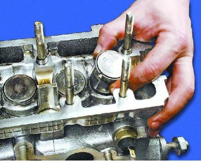
24. Remove the valve lifters together with the adjusting washers.
Valve drive parts: 1 – exhaust valve; 2 – inlet valve; 3 – outer spring; 4 – internal spring; 5 –…

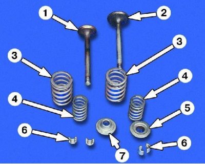
Valve drive parts: 1 – exhaust valve; 2 – inlet valve; 3 – outer spring; 4 – internal spring; 5 – spring plate; 6 – crackers; 7 – spring support washer

Valve drive parts: 1 – exhaust valve; 2 – inlet valve; 3 – outer spring; 4 – internal spring; 5 –…


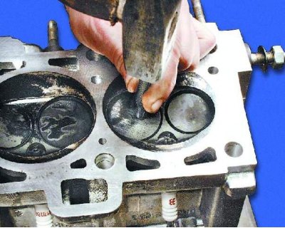
25. Mark the valves with the cylinder number so that they can be installed in their proper places during assembly. The marking can be applied using a punch as close to the center of the valve as possible: the valves of the first cylinder - one dot, the second - two, etc.
25. Mark the valves with the cylinder number so that they can be installed in their proper places…


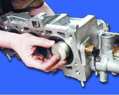
26. Place a suitable stop under the valve to be removed.
26. Place a suitable stop under the valve to be removed.


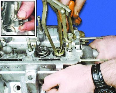
27. Install a valve spring compressor on the head. Compress the valve springs with it and remove the crackers. Gradually loosen the pressure on the handle of the compressor, completely release the valve spring and remove the compressor from the head.
27. Install a valve spring compressor on the head. Compress the valve springs with it and remove…


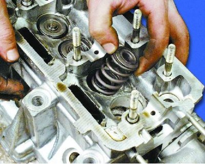
28. Remove the outer spring with the plate.
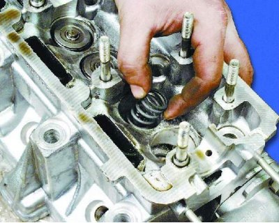
28. Remove the outer spring with the plate.


29. Remove the inner spring.
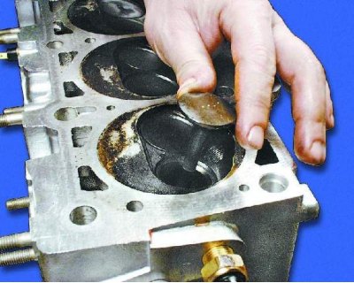
29. Remove the inner spring.


30. Remove the valve from the cylinder head.
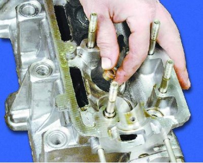
30. Remove the valve from the cylinder head.


31. Carefully remove the valve stem seal without damaging the valve guide.
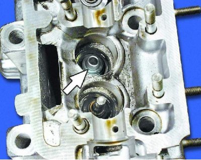
31. Carefully remove the valve stem seal without damaging the valve guide.


32. Remove the valve spring support washer (plate). Remove the remaining valves in the same manner.


This article is available at russian, bulgarian, belarusian, ukrainian, serbian, croatian, romanian, polish, slovak, hungarian
The text was reviewed by the specialist: Grigory Vologodtsev

Share with friends:

Previous articles
VAZ-21099: Engine repair
Next articles

Cylinder head — design description
Piston with connecting rod — disassembly, defect detection and assembly
Cylinder block — inspection, defect detection and repair
Complete disassembly of the engine
Adjusting valve clearances
Inspection and defect detection of parts
Lapping valves
Replacing valve guide bushings
Cylinder head assembly
Engine assembly

More articles from other manuals on VAZ cars:
➠ Disassembling the cylinder head, grinding the valves VAZ-21061 (1976-2006)
➠ Removal and disassembling the cylinder head of an injection… VAZ-21214 (1994-2006)
➠ Replacing the cylinder head gasket VAZ-11113 (1996-2003)
➠ Parting plane with cylinder head VAZ-21011 (1974-1983)
➠ Cylinder head design VAZ-2105 (1979-2010)
Link in different formats to this page


Visitor comments

No comments yet


How much will 44 + 12 ?


VAZ-21099 (1990-2004) 
  • General information
  • Specifications
  • User manual
  • Maintenance
  • Car care
  • Troubleshooting
  • Power unit
  • Engine repair
  • Cooling and lubrication system
  • Power and exhaust system
  • Transmission
  • Car gearbox
  • Clutch and drive shafts
  • Chassis
  • Car suspension
  • Steering
  • Brake system
  • Body
  • Exterior
  • Interior
  • Doors and locks
  • Electrical equipment
  • Equipment and devices
  • Lighting and signaling
  • Engine electrics
  • Ignition system


VAZ-2109 (1984-1997) 
  • General information
  • Vehicle operation
  • Vehicle device
  • Power unit
  • Engine repair
  • Cooling and lubrication system
  • Supply system
  • Transmission
  • Clutch
  • Gearbox and drive
  • Chassis
  • Car suspension
  • Steering
  • Brake system
  • Body
  • Body elements
  • Electrical equipment
  • Engine electrics
  • Equipment and devices


VAZ-2108 (1984-2003) 
  • General information
  • Introduction to guide
  • Power unit
  • Engine repair
  • Cooling and lubrication system
  • Power and exhaust system
  • Transmission
  • Clutch and drive shafts
  • Car gearbox
  • Chassis
  • Front suspension
  • Rear suspension
  • Steering
  • Brake system
  • Body
  • Exterior
  • Interior
  • Doors and glass
  • Electrical equipment
  • Equipment and devices
  • Engine electrics
  • Ignition system


VAZbook.ru © 2017 · Mobile version · Contact with administration · Sitemap: EN BG BY UA RS HR RO PL SK HU · Site search · News and articles VAZ-1111 · VAZ-11113 · VAZ-2101 · VAZ-21011 · VAZ-2104 · VAZ-2105 · VAZ-21051 · VAZ-2106 · VAZ-21061 · VAZ-2107 · VAZ-21099 · VAZ-2109 · VAZ-2108 · VAZ-2110 · VAZ-2112 · VAZ-2114 · VAZ-2115 · VAZ-2121 · VAZ-21213 · VAZ-21214 ·
The site stores technical data using cookies to improve the service.