




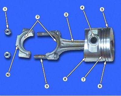
Piston with connecting rod: 1 - connecting rod bolt nut; 2 - connecting rod bearings; 3 - connecting rod; 4 - piston pin; 5 - groove of the upper compression ring; 6 - groove of the lower compression ring; 7 - oil scraper ring groove; 8 - piston; 9 - connecting rod bolt; 10 - connecting rod cover
For ease of selection of pistons for cylinders, cylinders and pistons are divided into five size groups depending on diameter: A, B, C, D, E.
Pistons of nominal size of three classes are supplied as spare parts: A, C, E and two repair sizes. The first repair size is increased by 0.4 mm, the second by 0.8 mm.
According to weight, pistons are divided into three groups: normal, increased by 5 g and decreased by 5 g. Pistons of the same group must be installed on the engine.
For pistons of repair sizes, rings of repair sizes increased by 0.4 mm and 0.8 mm are supplied as spare parts. The rings of the first repair size are stamped with the number "40", and the second - "80".
Nominal dimensions of cylinders and pistons
| Size group | Engine model VAZ-2108 | Engine model VAZ-21083 | ||
Cylinder diameter, mm | Piston diameter, mm | Cylinder diameter, mm | Piston diameter, mm | |
A | 76,00-76,01 | 75,965-75,975 | 82,00-82,01 | 81,965-81,975 |
B | 76,01-76,02 | 75,975-75,985 | 82,01-82,02 | 81,975-81,985 |
C | 76,02-76,03 | 75,985-75,995 | 82,02-82,03 | 81,985-81,995 |
D | 76,03-76,04 | 75,995-76,005 | 82,03-82,04 | 81,995-82,005 |
E | 76,04-76,05 | 76,005-76,015 | 82,04-82,05 | 82,005-82,015 |
To select pistons for cylinders, calculate the clearance between them. The clearance is defined as the difference between the measured diameters of the piston and cylinder. The nominal clearance is 0.025-0.045 mm, the maximum allowable is 0.15 mm. If the clearance does not exceed 0.15 mm, you can select pistons from the following classes so that the clearance is as close to the nominal as possible. If the clearance exceeds 0.15 mm, bore the cylinders to the next repair size and install pistons of the corresponding repair size.
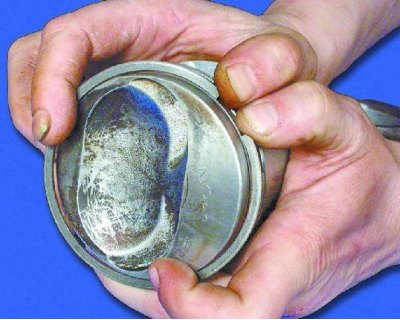
1. We recommend removing piston rings with a special puller. If you don't have one, carefully spread the ring lock and remove the ring from the piston. Remove the remaining rings in the same way.
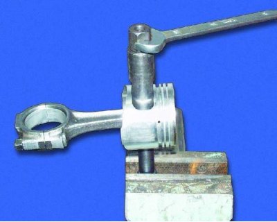
2. Using a special mandrel, press the pin out of the connecting rod.
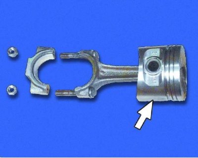
3. Inspect the pistons. If they have scoring, burn marks, deep scratches, replace the pistons.
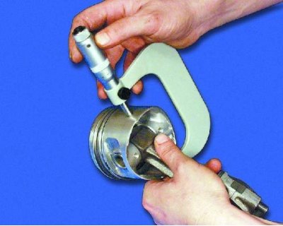
4. To determine the clearance, measure the cylinder diameter (see subsection 11.8.) and the piston diameter, which is measured with a micrometer in a plane perpendicular to the axis of the piston pin, at a distance of 51.5 mm from the piston bottom.
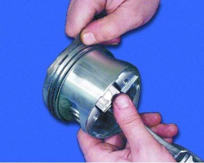
5. Measure the gap between the rings and the grooves on the piston in several places around the perimeter with a feeler gauge. If the gap exceeds the maximum permissible (see note 1), replace pistons with rings.
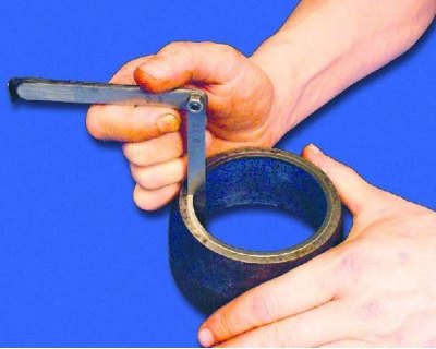
6. Insert the piston ring into a special mandrel and measure the gap in the lock. Instead of a mandrel, you can insert the ring into the cylinder and push it with the piston so that the ring fits without distortions. If the gap exceeds the maximum permissible, replace the ring (see note 2). If the gap is less than 0.25 mm, carefully file the ends of the ring.
Note 1
Clearance between rings and piston grooves, mm | |
Nominal: | |
upper compression ring | 0,04-0,075 |
lower compression ring | 0,03-0,065 |
oil scraper ring | 0,02-0,055 |
Maximum permissible clearance for all rings | 0,15. |
Note 2
| Piston ring gap, mm: | |
Nominal | 0,25-0,45 |
Maximum permissible | 1,0 |
Piston pins are divided into three classes by diameter (1st, 2nd, 3rd) through 0.004 mm. The finger class is marked on its end with paint.
Classes of piston pins and pistons
| Class | Pin diameter, mm | Piston bore diameter, mm | Marking | |
fingers | piston | |||
1 | 21,970-21,974 | 21,982-21,986 | Blue | 1 |
2 | 21,974-21,978 | 21,986-21,990 | Green | 2 |
3 | 21,978-21,982 | 21,990-21,994 | Red | 3 |
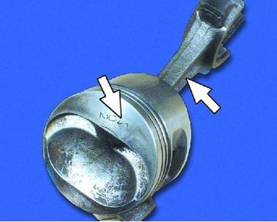
The piston is installed on the connecting rod so that the arrow on the piston bottom is directed in the opposite direction from the part number cast on the connecting rod. If there is a hole for oil outlet on the lower head of the connecting rod, the arrow on the piston should be directed towards this hole.
7. Check the fit of the piston pin in the piston. To do this, lubricate the piston pin with engine oil and insert it into the piston. The pin should enter the piston freely without pressing with your thumb.
8. Turn the piston over so that the pin stands vertically, but it should not fall out of the piston under its own weight. If the pin falls out of the piston, take the pin of the next class. If the pin of the third class falls out of the piston, replace the piston and the pin.
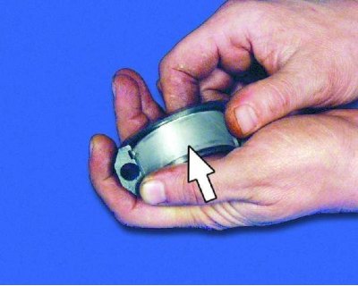
9. Inspect the connecting rod bearings. If they have cracks, scoring, or chipping, replace the bearings.
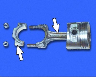
10. Inspect the connecting rods with caps. Replace bent connecting rods.
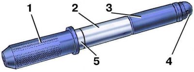
11. Place piston pin 2 on shaft 1 of the piston pin installation device with spacer ring 5 placed on it. Then place guide sleeve 3 and secure it with screw 4 without tightening the screw. Dimensions of the spacer ring: outer diameter 22 mm, inner diameter 15 mm, thickness 4 mm.
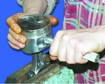
12. Heat the upper head of the connecting rod to 240°C in the oven for 15 minutes. Clamp the connecting rod in a vice, install the piston on it (see note), so that the holes for the pin match, and insert the device with the pin into the holes of the piston and connecting rod until it stops. For correct installation of the pin, the piston must be pressed with the boss against the upper head of the connecting rod in the direction of pressing.
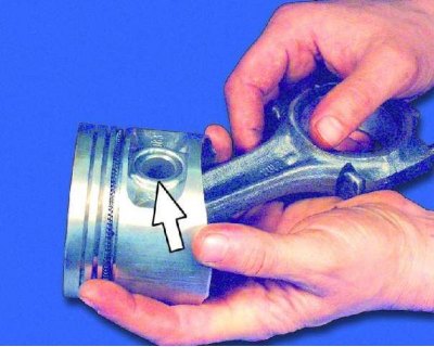
13. After the connecting rod has cooled, lubricate the piston pin through the hole in the piston crowns.
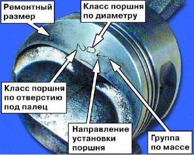
The connecting rods are processed together with the caps, so they cannot be disassembled.
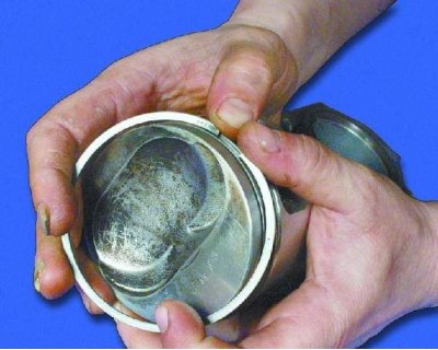
If new parts are installed during the assembly of the connecting rod and piston group, select pistons for cylinders by class, group and weight. Piston pins and pistons also need to be selected by class.
Note: The piston and connecting rod assembly should be done as quickly as possible, as the connecting rod cools down quickly. Once the connecting rod has cooled down, it will be impossible to change the position of the pin.
Designation of repair size:
- 1st repair - triangle,
- 2nd repair - square.
Designation of group by mass:
- normal - "G",
- increased by 5 grams - "+",
- reduced by 5 grams – "-".
14. Lubricate the piston rings and piston grooves with engine oil. Put the piston rings on with a puller or manually, orienting them accordingly. Check that the rings move easily in the grooves.
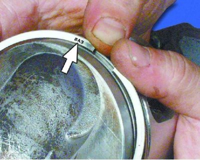
15. If the ring has the inscription "Top" or "VAZ", install the ring with the inscription facing up, towards the bottom of the piston.
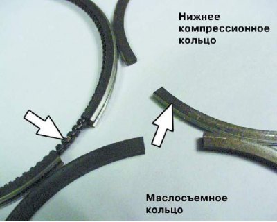
16. There is a groove on the lower compression ring. The ring should be installed with the groove facing down. Before installing the oil scraper ring, turn the spring expander so that its lock is on the opposite side from the ring lock.
17. Rotate the piston rings so that their ring ends are at an angle of 120° to each other.
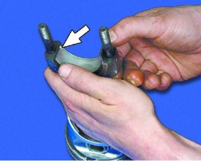
18. Insert the bearing shell into the lower connecting rod head, ensuring that the locking lug on the bearing shell fits into the groove in the connecting rod head.
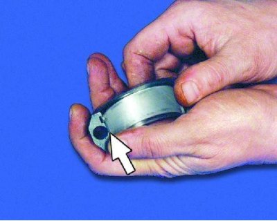
19. Insert the bearing shell into the connecting rod cap so that the locking tab on the bearing shell fits into the groove in the connecting rod cap.