




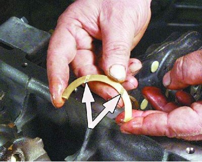
Attention! The thrust half rings have an antifriction layer on the groove side. This side of the half rings should be installed towards the crankshaft cheeks.
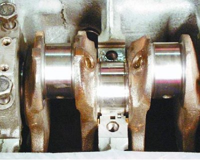
From the front of the bed (from the camshaft drive side) a steel-aluminum half ring is installed (white color), and on the other hand - metal-ceramic (yellow color).
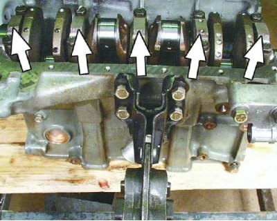
The main bearing caps have marks in the form of notches: one on the first, two on the second, three on the third, four on the fourth, and two on the fifth. On the second cap, in addition to the marks, there are two holes for fastening the oil pump receiver. The first is the cap on the camshaft drive side.
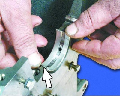
1. Install the liners in the main bearing beds. The retaining lug of the liners should fit into the bed groove. In the first, second, fourth and fifth beds (counting from the camshaft drive) install liners with grooves, and in the third - without grooves.
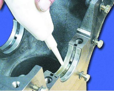
2. Lubricate the bearings with engine oil.
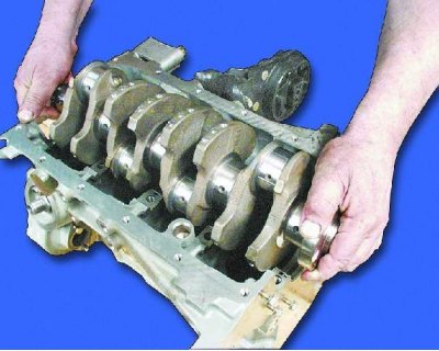
3. Lubricate the crankshaft journals with engine oil and place the shaft in the main bearing beds. The flywheel mounting flange should be located on the fourth cylinder side.
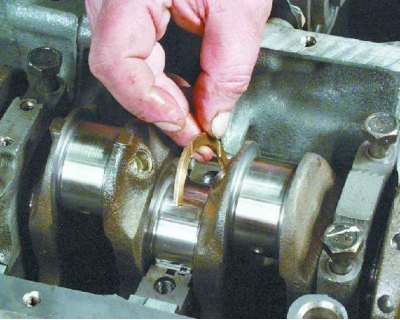
4. Insert two thrust half rings into the grooves of the third main bearing bed.
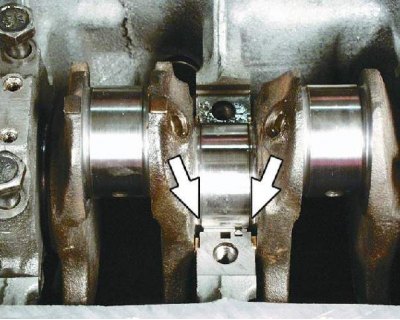
5. Rotate the half rings so that their ends are flush with the ends of the bed.
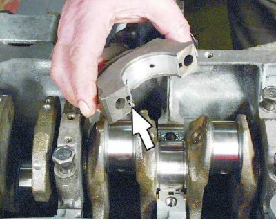
6. Insert the inserts into the non-grooved insert covers. In this case, the fixing protrusion of the insert must enter the slot of the cover.

7. Lubricate the cover insert with engine oil. Install the cover in place according to the mark.
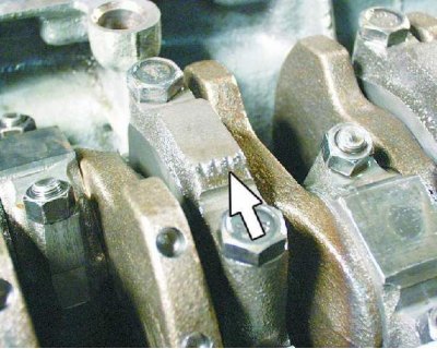
8. The cover is installed so that the mark on it is located on the generator side (on the left side of the engine). Install the remaining covers in the same manner according to the marks.
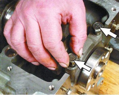
9. Tighten the cover mounting bolts without tightening them.
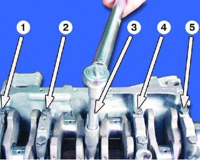
10. Tighten the cover mounting bolts to a torque of 69-84 N·m (6.9-8.4 kgf·m). Tighten the third cover bolts first, then the second and fourth, then the first and fifth. After tightening the bolts, turn the crankshaft - it should rotate easily, without jamming.
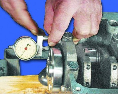
11. Using an indicator, measure the axial clearance of the crankshaft. It should be within 0.06-0.26 mm. If the clearance exceeds 0.26 mm, replace the thrust half rings (see note 1).
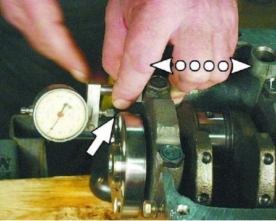
Note 1: To measure the crankshaft end play, set the indicator so that its foot rests against the shaft flange. Move the crankshaft as far away from the indicator as possible and set the indicator to 0. Move the crankshaft in the opposite direction. The indicator will show the clearance value.
Note 2: Nominal size half rings are supplied as spare parts (thickness 2.31-2.36 mm) and increased in size by 0.127 mm (thickness 2.437-2.487 mm).
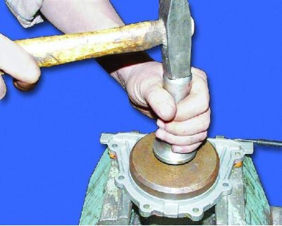
12. Using a drift, press the rear crankshaft oil seal into the holder until it stops.
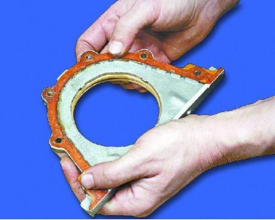
13. Use grease to adhere the retainer gasket to the seal retainer for ease of installation.
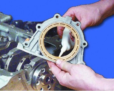
14. Lubricate the working lip of the oil seal with engine oil.
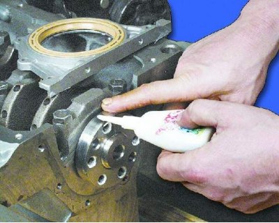
15. Lubricate the crankshaft flange with engine oil.
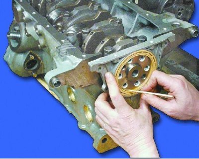
16. The rear crankshaft oil seal is installed in the holder using a special mandrel. If there is no mandrel, place the oil seal with the holder on the crankshaft flange, carefully tucking the working edge of the oil seal onto the shaft flange using a pointed stick made of soft wood.
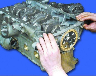
17. Carefully slide the holder along the flange until it stops and tighten the mounting bolts.
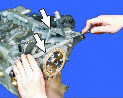
18. Adjust the holder so that its upper plane coincides with the plane of the block.
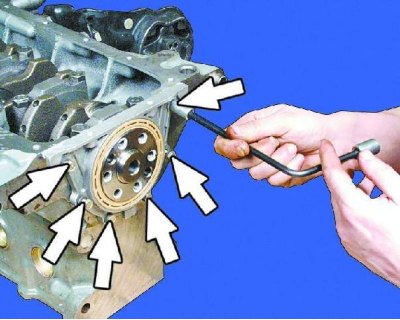
19. Tighten the six bracket mounting bolts.
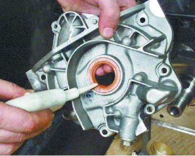
20. Press the front crankshaft oil seal into the oil pump housing using a drift. Lubricate the working edge of the seal with engine oil.
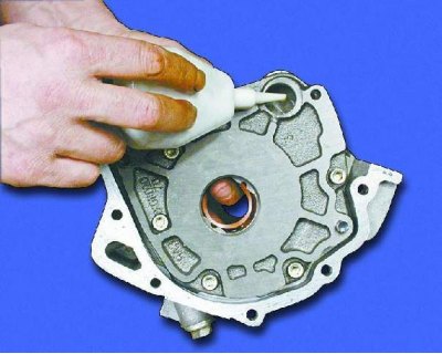
21. Lubricate the oil pump gears with engine oil by pouring oil through the hole under the oil receiver.
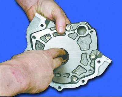
22. Turn the oil pump gears several times using the pinion gear lugs.
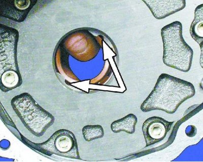
23. Rotate the oil pump drive gear to properly install it on the crankshaft: the projections on the drive gear must match...
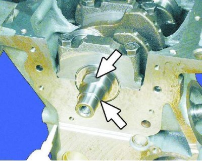
24....with chamfers on the crankshaft.
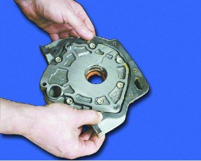
25. Apply grease to the sealing gasket on the pump for ease of installation.
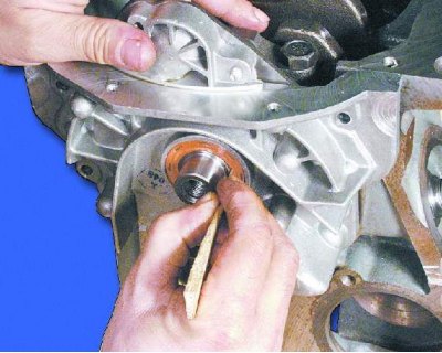
26. The front crankshaft oil seal is installed using a special mandrel. If there is no mandrel, put the pump with the oil seal on the crankshaft until it reaches the seat on the shaft. Then, using a pointed stick made of soft wood, carefully tuck the working edge of the oil seal onto the shaft journal.
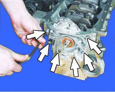
27. Carefully slide the oil pump along the shaft until it stops and tighten the mounting bolts. Adjust the position of the pump so that its upper plane coincides with the plane of the block. Tighten the six mounting bolts with a torque of 8.5-10.0 N·m (0.85-1.0 kgf·m).
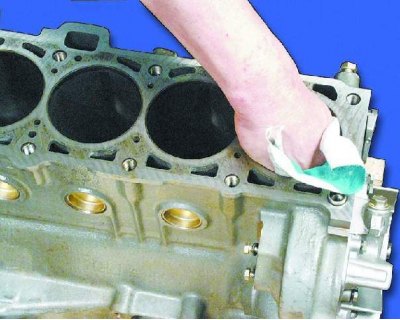
28. Wipe the cylinder mirrors thoroughly...

29....and the crankshaft journals with a soft, lint-free cloth.
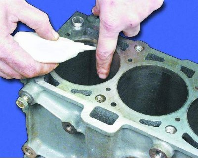
30. Lubricate the mirror of the first cylinder with engine oil.
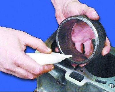
31. Lubricate the piston installation mandrel with engine oil.
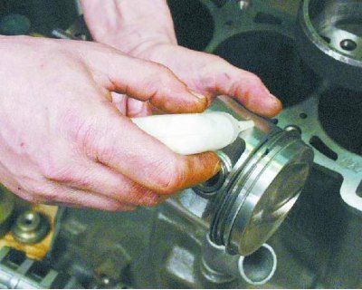
32. Lubricate the piston of the 1st cylinder with engine oil.

33. Spread the piston ring locks at an angle of 120° relative to each other.
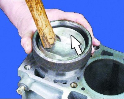
34. Insert the piston assembly with the connecting rod into the mandrel and use it to install the piston into the cylinder so that the arrow on the bottom of the piston points towards the oil pump.
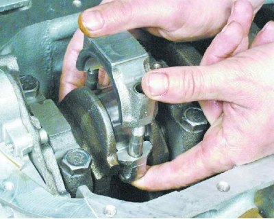
35. Install the connecting rod cap with the bearing shell in accordance with the marking, having previously lubricated the bearing shell with engine oil (see note).
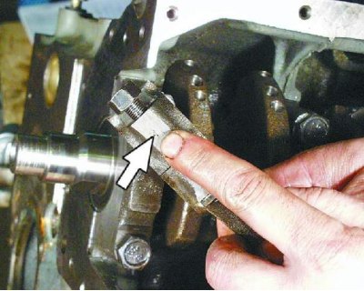
Note: The connecting rod caps are installed so that the cylinder numbers on the cap and connecting rod are located on the same side.
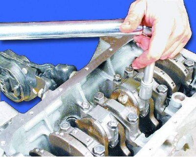
36. Tighten the two cover mounting nuts. Install the remaining pistons in the same manner.
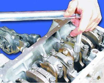
37. Tighten the connecting rod cap nuts with a torque wrench to 44-54 N·m (4.4-5.4 kgf·m).
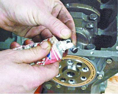
38. Apply a thin layer of sealant to the threads of the flywheel mounting bolts.
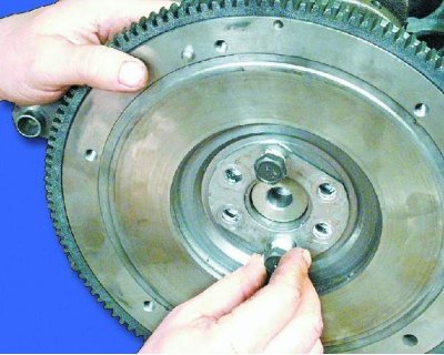
39. Install the flywheel, then the lock washer and tighten the flywheel mounting bolts (see note).
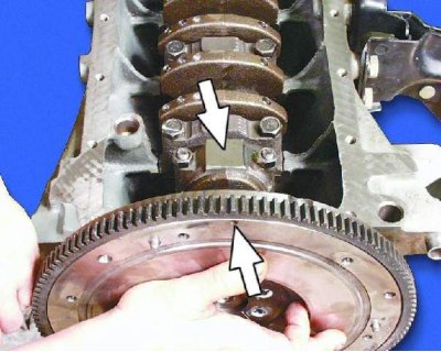
Note: Install the flywheel so that the mark on the flywheel is opposite the connecting rod cap of the fourth cylinder, since the mounting bolts are located asymmetrically.

40. Tighten the flywheel mounting bolts to 62-89 N·m (6.2-8.9 kgf·m), holding the flywheel from turning.
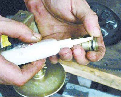
41. Lubricate the oil pan sealing ring with engine oil.
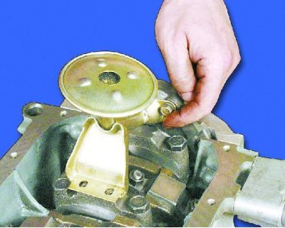
42. Install the oil receiver in place (see note) and tighten the bolt securing the oil receiver to the oil pump with a torque of 7.0-8.0 N·m (0.7-0.8 kgf·m).
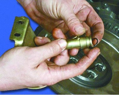
Note: We recommend replacing the oil receiver sealing ring before installation.
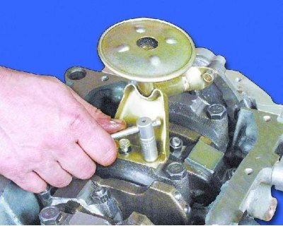
43. Tighten the two bolts securing the oil receiver to the cover of the second main bearing with a torque of 8-10 N·m (0.8-1.0 kgf·m).
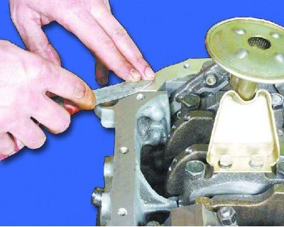
44. Cut off the protruding ends of the seal retainer and oil pump gaskets.
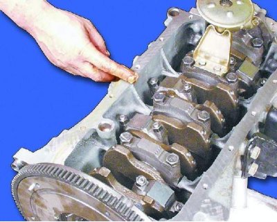
45. Lubricate the mating surface of the cylinder block with consistent grease.
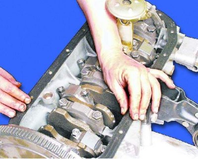
46. Install the oil pan gasket.

47. Install the oil pan.
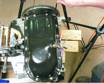
48. Tighten the oil pan mounting bolts to a torque of 5-8 N·m (0.5-0.8 kgf·m).
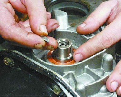
49. Install the key into the crankshaft groove.
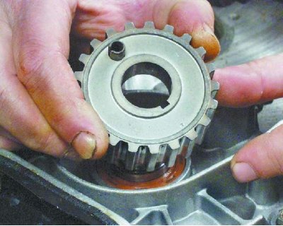
50. Install the crankshaft pulley with the pin facing out.
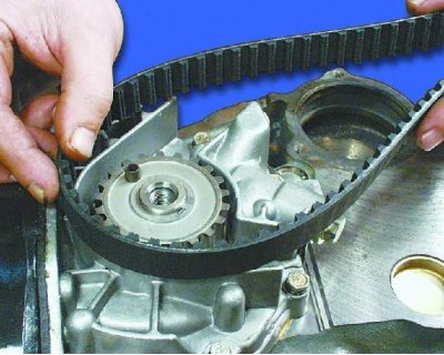
51. Place the timing belt on the crankshaft pulley.
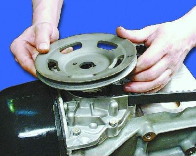
52. Install the pulley onto the crankshaft, aligning the hole in the pulley with the pin on the timing belt pulley.
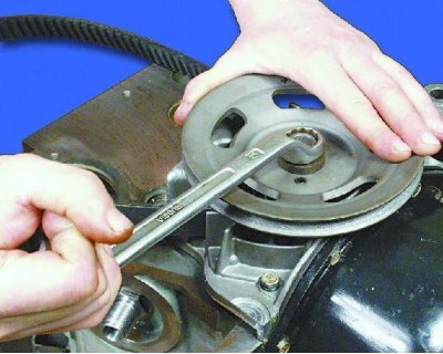
53. Tighten the pulley mounting bolt with the washer to a torque of 99.0-110.0 N·m (9.9-11.0 kgf·m), securing it from turning.
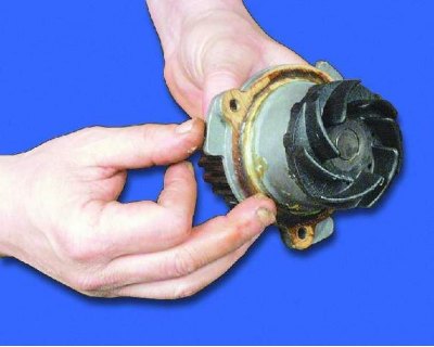
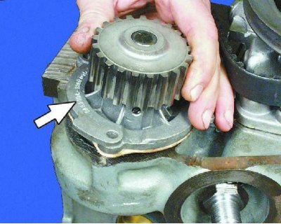
54. Install the sealing gasket onto the water pump and lubricate the gasket with grease.
The original can be viewed on the portal: VAZbook.ru
55. Install the water pump into the cylinder block so that the factory marking on the pump faces the mating surface of the cylinder block, as the mounting bolts are located asymmetrically.
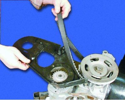
56. Install the rear camshaft drive cover.
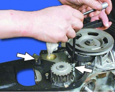
57. Tighten the four bolts securing the rear cover to the cylinder block with a torque of 7.8–8.0 N·m (0.78–0.80 kgf·m).
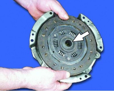
58. Install the driven disc into the pressure plate housing so that the less protruding part of the hub is directed towards the flywheel.
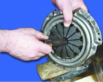
59. Insert the centering mandrel into the splines of the driven disk from the diaphragm spring side.
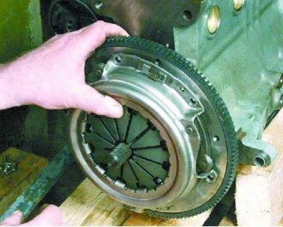
60. Install the clutch onto the flywheel.
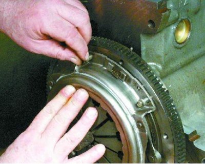
61. Tighten the six clutch-to-flywheel mounting bolts evenly diagonally to a torque of 19.0-31.0 N·m (1.9-3.1 kgf·m). We recommend replacing the mounting bolts during assembly.
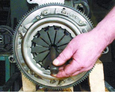
62. Remove the centering mandrel.