




The gap is measured on a cold engine (at 20°C) between the camshaft cam (the cam must be directed upwards from the pushrod) and the valve tappet adjusting washer.
The nominal clearance for the inlet valve is (0.2+0.05) mm, for the outlet valve - (0.35+0.05) mm. Clearances are adjusted by selecting the thickness of the adjusting washers. Washers with a thickness of 3 to 4.5 mm in 0.05 mm increments are supplied as spare parts.
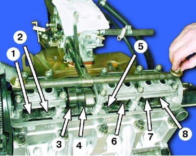
Counting from the camshaft drive, the first, fourth, fifth and eighth valves are exhaust valves; the second, third, sixth and seventh are inlet.
Note: It is recommended to remove the spark plugs to make it easier to turn the crankshaft.
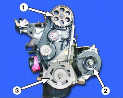
1-camshaft gear wheel
2 – generator pulley
3 – crankshaft pulley
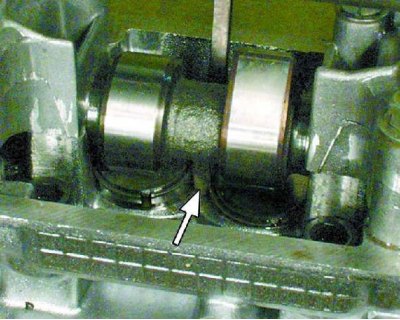
The retainer must be installed between the camshaft and the edge of the tappet.
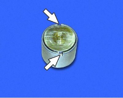
To make it easier to remove the adjusting washer, two grooves are machined in the pusher. Turn the pusher so that it is easier to hook the washer.
The thickness of the new washer is calculated using the formula: H = B + A – C,
where A is the measured gap, mm;
B – thickness of the old washer, mm;
C – nominal clearance, mm;
H – thickness of the new washer, mm.
Example (for intake valve): A = 0.26 mm, B = 3.75 mm, C = 0.2 mm, then
H = 3.75 + 0.26 – 0.2 = 3.81 (mm).
Within the clearance tolerance of +0.05 mm, we select the closest washer in thickness (3.8 mm).
Caution! Turn the crankshaft clockwise using the wrench on the crankshaft pulley mounting bolt or the alternator pulley mounting bolt. Do not turn the crankshaft using the camshaft pulley mounting bolt.
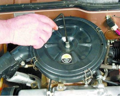
1. Unscrew the filter cover mounting nut and remove the washer.
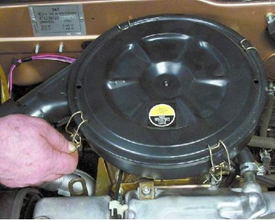
2. Unfasten the four spring clips.
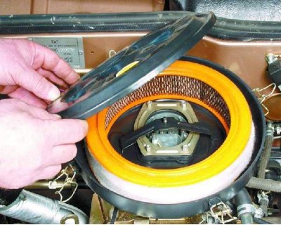
3. Remove the air filter cover.
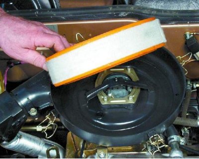
4. Remove the filter element from the housing.
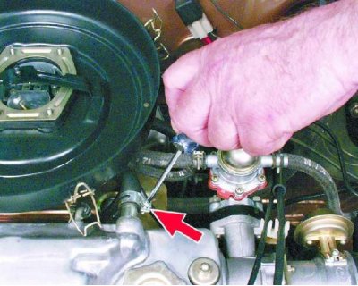
5. Loosen the clamps and remove the hoses from the fittings on the valve cover.
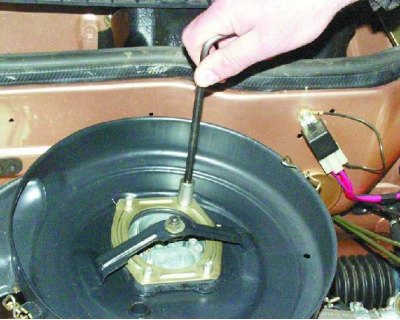
6. Unscrew the four nuts.
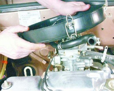
7. Remove the filter housing from the studs and the warm air intake hose from the branch pipe. Disconnect the hose from the filter housing, having first loosened the clamp.
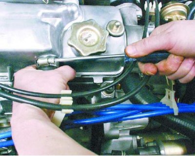
8. Disconnect the plastic holder from the hose, loosen the clamp and remove the hose from the branch pipe on the valve cover.
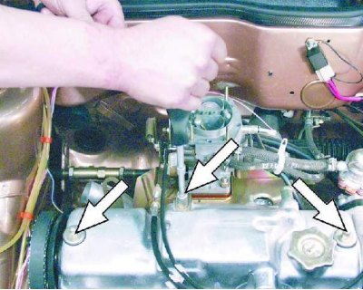
9. Loosen the nut and remove the accelerator cable bracket, leaving it hanging on the cable. Loosen the two cap nuts.
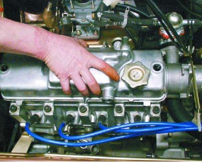
10. Remove the valve cover.
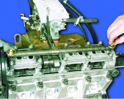
11. Remove oil from the top of the cylinder head (around the valve lifters). Install the tappet driver onto the valve cover mounting studs and secure with nuts.
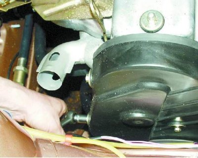
12. Remove the three bolts and the front camshaft drive cover.
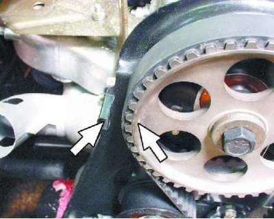
13. Set the piston of the first cylinder to TDC of the compression stroke. To do this, turn the crankshaft so that the mark on the camshaft pulley coincides with the mark (antenna) on the rear cover of the camshaft drive (see notes). Then turn the crankshaft another 40-50°. This will cause the camshaft cams to turn away from the tappets.
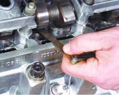
14. Measure the clearances at the first, second, third and fifth valves using a set of feeler gauges.
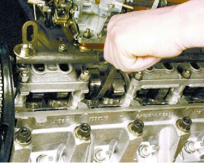
15. If the clearance of any valve differs from the nominal value, press the pusher of this valve by pressing the handle of the device.
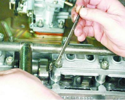
16. While holding the plunger in the recessed position, install the locking pin (see notes).
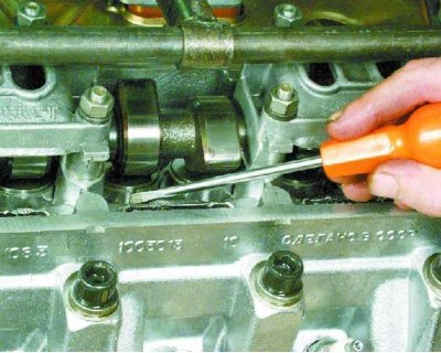
17. Move the countersink away from the pushrod and remove the adjusting washer by prying it up with a thin screwdriver (see notes).
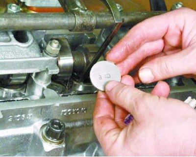
18. Record the thickness of the adjusting shim, which is marked on one side. If the thickness of the shim is not visible, measure it with a micrometer.
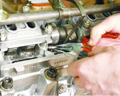
19. Install a new washer of the required thickness into the pusher (see notes). Install the washer with the inscription facing down (to the pusher). Press the plunger with the tool and remove the retainer.
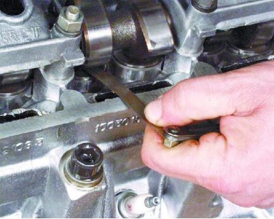
20. To check, measure the gap with a feeler gauge: if it differs from the nominal value, repeat the adjustment.
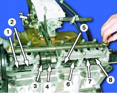
21. Turn the crankshaft one revolution (360°) and adjust the clearances of the fourth, sixth, seventh and eighth valves in the same order. Then pour oil into the upper part of the cylinder head.
22. Install the front camshaft cover, valve cover, air cleaner and spark plugs. Tightening torques see Appendix 3.