English Русский
Български
Беларускі
Український
Српски
Hrvatski
Română
Polski
Slovenský
Magyar
| Articles | Contacts | Sitemap |   
Repair and maintenance Lada Repair and maintenance Mazda Repair and maintenance Mitsubishi Repair and maintenance Toyota Repair and maintenance Land Rover Repair and maintenance Hyundai Repair and maintenance Nissan
VAZbook.ru


Main     1111   2101   2105   2106   2107   2109   2110   2115   2121  
VAZ-2108 (1984-2003) VAZ-2109 (1984-1997) VAZ-21099 (1990-2004)
  • Main
  • «Sputnik»
  • VAZ-21099
  • Power unit
  • Engine repair
  • Complete disassembly of the engine

Complete disassembly of the engine (VAZ-21099)

            0

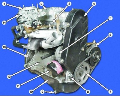
Engine appearance: 1 - carburetor; 2 - valve cover; 3 - cylinder head; 4 - front cover; 5 - water…

Engine appearance: 1 - carburetor; 2 - valve cover; 3 - cylinder head; 4 - front cover; 5 - water pump; 6 - generator; 7 - crankshaft pulley; 8 - oil pump; 9 - drain plug; 10 - oil pan; 11 - oil filter; 12 - cylinder block; 13 - flywheel; 14 - fuel pump


Caution! Be sure to hold the flywheel.


1. Place the engine on sturdy supports.
1. Place the engine on sturdy supports.


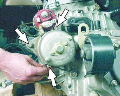
2. Unscrew the three starter mounting nuts.
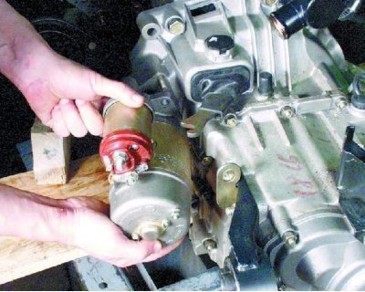
2. Unscrew the three starter mounting nuts.


3. Remove the starter.
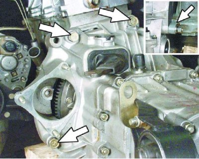


3. Remove the starter.


4. Remove the three bolts and nut securing the gearbox to the cylinder block.
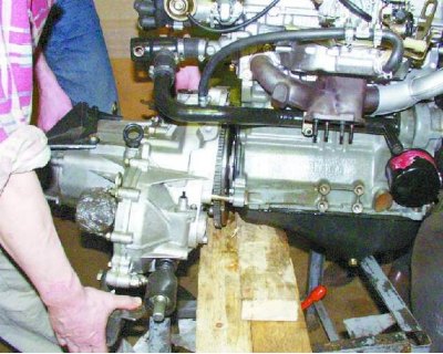
4. Remove the three bolts and nut securing the gearbox to the cylinder block.


5. Carefully remove the gearbox, making sure that the splined end of the input shaft does not rest on the diaphragm spring petals.
5. Carefully remove the gearbox, making sure that the splined end of the input shaft does not rest…


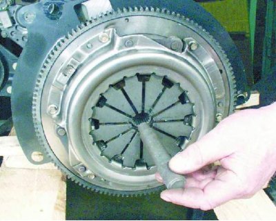
6. Insert the mandrel into the hole in the pressure plate.

You can remove the clutch without a mandrel, but you need to hold the driven disk - it can fall out of the clutch housing.


The mandrel can be made to the dimensions of the primary shaft or the old primary shaft can be used instead.
The mandrel can be made to the dimensions of the primary shaft or the old primary shaft can be used…


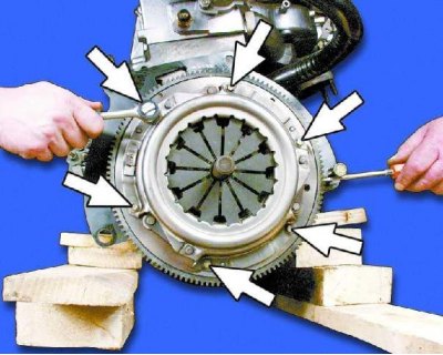
7. Unscrew the six bolts securing the clutch housing to the flywheel, blocking the flywheel with a screwdriver. Install a bolt of a suitable diameter to support the screwdriver.
7. Unscrew the six bolts securing the clutch housing to the flywheel, blocking the flywheel with a…


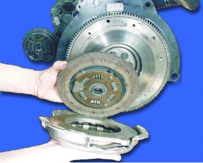
8. Carefully remove the clutch cover together with the driven disk.
8. Carefully remove the clutch cover together with the driven disk.


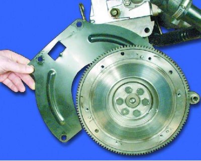
9. Remove the upper clutch housing cover from the mounting pins, rotate it and remove it from behind the flywheel
9. Remove the upper clutch housing cover from the mounting pins, rotate it and remove it from…


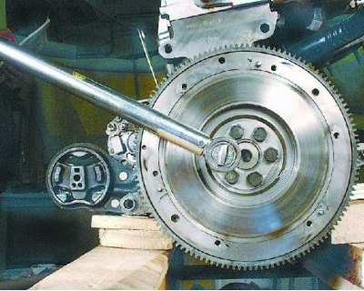
10. Loosen the six flywheel mounting bolts, securing it from turning. Remove the locking plate while holding the flywheel.
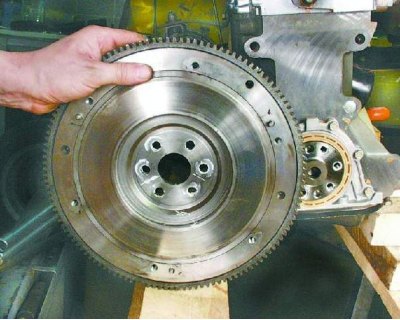
10. Loosen the six flywheel mounting bolts, securing it from turning. Remove the locking plate…


11. Remove the flywheel from the crankshaft.
11. Remove the flywheel from the crankshaft.


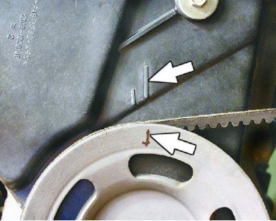
12. Set the piston of the first cylinder to TDC of the compression stroke. To do this, turn the crankshaft with a wrench by the bolt until the mark on the crankshaft pulley coincides with the long mark on the front cover.
12. Set the piston of the first cylinder to TDC of the compression stroke. To do this, turn the…


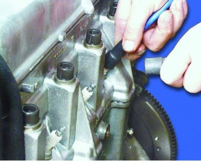
13. Remove the spark plug wire caps.

13. Remove the spark plug wire caps.
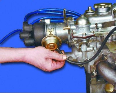

14. Disconnect the hose from the vacuum corrector.
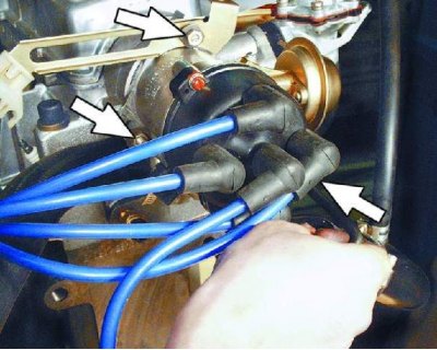
14. Disconnect the hose from the vacuum corrector.


15. Unscrew the three nuts securing the ignition distributor. Remove the bracket securing the high-voltage wires.
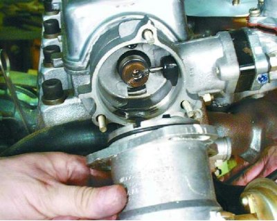
15. Unscrew the three nuts securing the ignition distributor. Remove the bracket securing the…


16. Remove the ignition distributor.

16. Remove the ignition distributor.
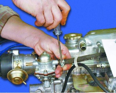

17. Loosen the clamp and disconnect the hose from the fuel pump.
17. Loosen the clamp and disconnect the hose from the fuel pump.


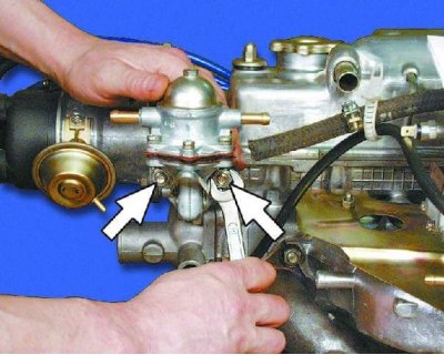
18. Unscrew the two fuel pump mounting nuts.
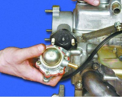
18. Unscrew the two fuel pump mounting nuts.


19. Remove the fuel pump carefully to avoid damaging the gasket.
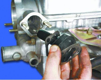
19. Remove the fuel pump carefully to avoid damaging the gasket.


20. Carefully remove the heat-insulating spacer with the rod, without damaging the adjusting linings.
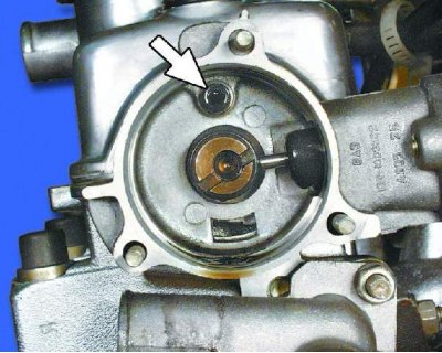
20. Carefully remove the heat-insulating spacer with the rod, without damaging the adjusting…


21. Remove the Allen key bolt securing the distributor drive housing (auxiliary units).
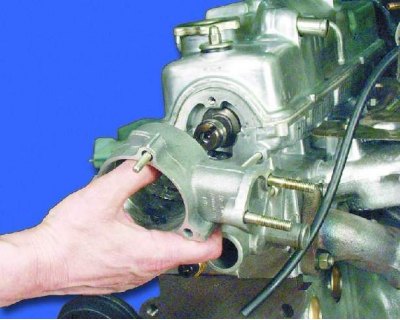
21. Remove the Allen key bolt securing the distributor drive housing (auxiliary units).


22. Remove the distributor drive housing (auxiliary units).

22. Remove the distributor drive housing (auxiliary units).
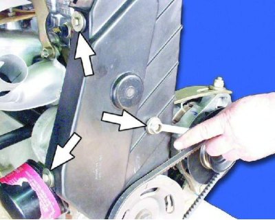

23. Remove the three bolts securing the front cover.
23. Remove the three bolts securing the front cover.


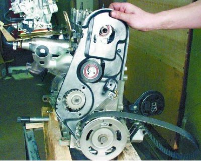
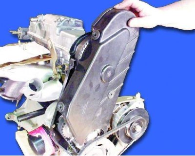
24. Remove the front cover.
24. Remove the front cover.


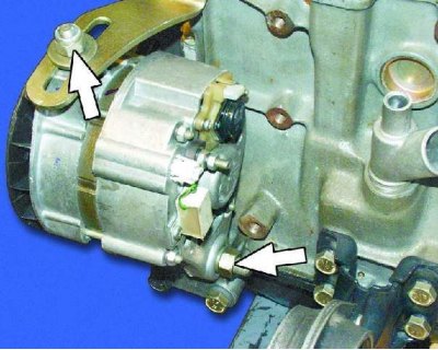
25. Loosen the generator mounting nuts.
25. Loosen the generator mounting nuts.


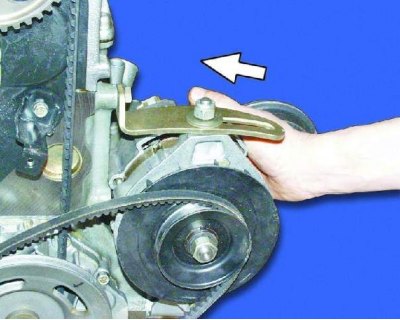
26. Turn the generator towards the block.
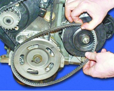
26. Turn the generator towards the block.


27. Remove the alternator drive belt.
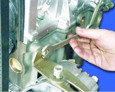
27. Remove the alternator drive belt.


28. Loosen the bolt securing the tension bar to the cylinder block.
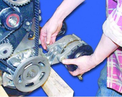
28. Loosen the bolt securing the tension bar to the cylinder block.


29. Completely loosen the generator mounting nut.
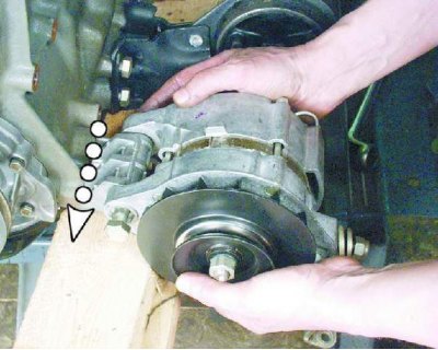
29. Completely loosen the generator mounting nut.


30. Remove the bolt while holding the generator and remove it from the engine.
30. Remove the bolt while holding the generator and remove it from the engine.


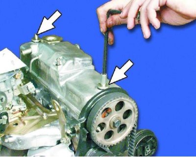
31. Unscrew the two cap nuts securing the valve cover.
31. Unscrew the two cap nuts securing the valve cover.


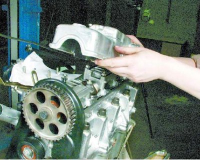
32. Carefully remove the valve cover together with the sealing gasket.
32. Carefully remove the valve cover together with the sealing gasket.


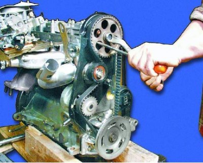
33. Loosen the camshaft pulley mounting bolt, holding it from turning by pressing a screwdriver against the rear cover mounting stud.
1 – tension roller; 2 – camshaft pulley; 3 – camshaft drive belt; 4 – generator pulley; 5 –…

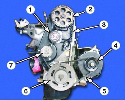
1 – tension roller; 2 – camshaft pulley; 3 – camshaft drive belt; 4 – generator pulley; 5 – alternator belt; 6 – crankshaft pulley; 7 – water pump pulley

1 – tension roller; 2 – camshaft pulley; 3 – camshaft drive belt; 4 – generator pulley; 5 –…


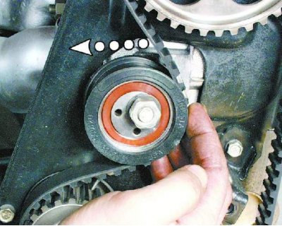
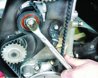
34. Loosen the tension roller nut.

34. Loosen the tension roller nut.


35. Turn the tension roller to loosen the belt tension.
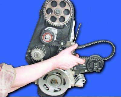
35. Turn the tension roller to loosen the belt tension.


36. Remove the belt from the camshaft pulley, tensioner pulley and water pump pulley.
36. Remove the belt from the camshaft pulley, tensioner pulley and water pump pulley.


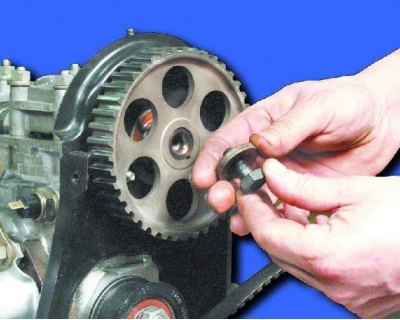
37. Loosen the camshaft pulley mounting bolt and remove it together with the washer.
37. Loosen the camshaft pulley mounting bolt and remove it together with the washer.


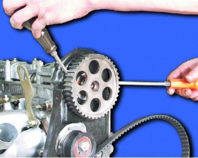
38. Carefully, so as not to damage the seal, press the camshaft pulley with a puller and remove it. If you do not have a puller, use two screwdrivers.
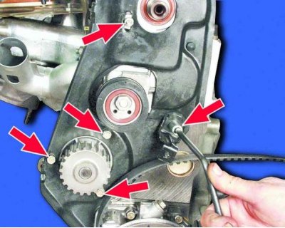
38. Carefully, so as not to damage the seal, press the camshaft pulley with a puller and remove it.…


39. Remove the back cover.

39. Remove the back cover.


40. Remove the four bolts and nut securing the rear cover.
40. Remove the four bolts and nut securing the rear cover.


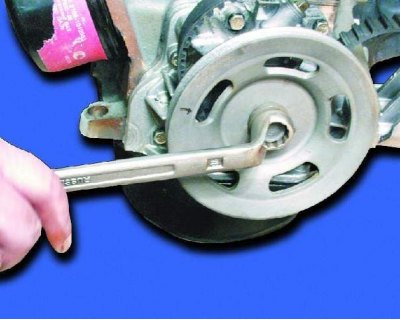
41. Loosen the crankshaft pulley mounting bolt while holding the shaft from turning.
41. Loosen the crankshaft pulley mounting bolt while holding the shaft from turning.


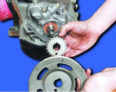
42. Remove the crankshaft pulley, timing pulley and timing belt.
42. Remove the crankshaft pulley, timing pulley and timing belt.


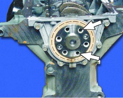
To prevent the crankshaft from turning, tighten the two flywheel mounting bolts into the holes in the crankshaft flange and insert a large screwdriver or pry bar between them.
To prevent the crankshaft from turning, tighten the two flywheel mounting bolts into the holes in…


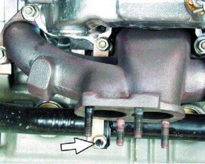
43. Loosen the mounting nut and disconnect the bracket from the water pump inlet pipe.
43. Loosen the mounting nut and disconnect the bracket from the water pump inlet pipe.


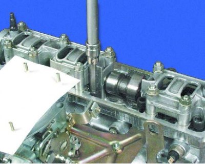
44. Unscrew the ten cylinder head mounting bolts using a special Allen key.
44. Unscrew the ten cylinder head mounting bolts using a special Allen key.


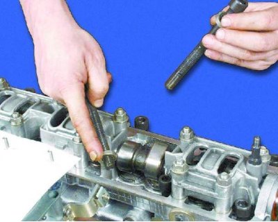
45. Remove the bolts and washers.
45. Remove the bolts and washers.


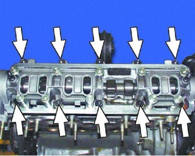
Location of cylinder head mounting bolts.
Location of cylinder head mounting bolts.


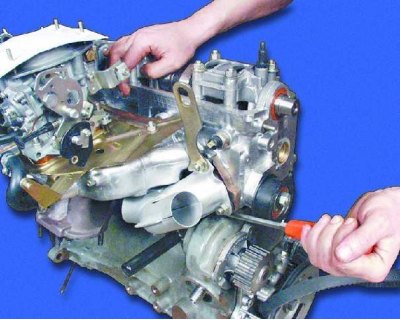
46. Remove the cylinder head.
46. Remove the cylinder head.


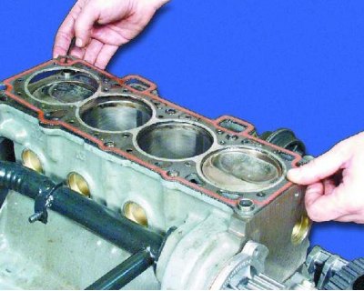
47. Remove the cylinder head gasket.
47. Remove the cylinder head gasket.


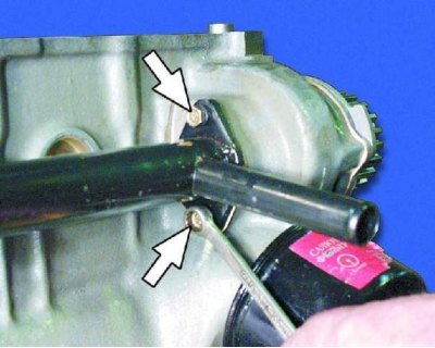
48. Loosen the two mounting bolts and remove the water pump inlet pipe.
48. Loosen the two mounting bolts and remove the water pump inlet pipe.


Warning for operation 46: Do not insert a screwdriver or other tools between the head and the cylinder block.


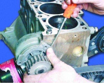
To pry the head off the block, insert a screwdriver under the exhaust manifold. Using it as a lever, lift the head.
To pry the head off the block, insert a screwdriver under the exhaust manifold. Using it as a…


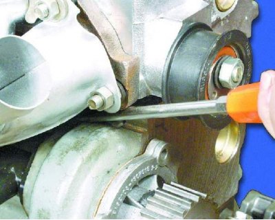
49. Remove the water pump by prying it out with a screwdriver.
49. Remove the water pump by prying it out with a screwdriver.


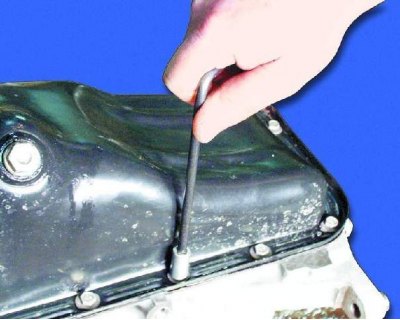
50. Turn the engine over with the oil pan facing up and remove the sixteen oil pan mounting bolts.
50. Turn the engine over with the oil pan facing up and remove the sixteen oil pan mounting bolts.


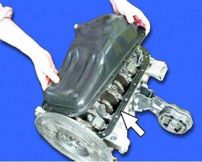
51. Remove the oil pan and sealing gasket.
51. Remove the oil pan and sealing gasket.


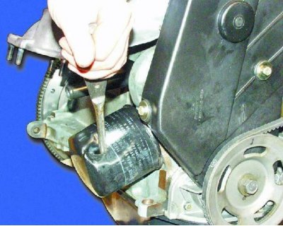
To remove the oil filter, use a special key. If you don't have a key and you can't unscrew the filter by hand, punch through its housing with a screwdriver and unscrew the filter, using the screwdriver as a lever.
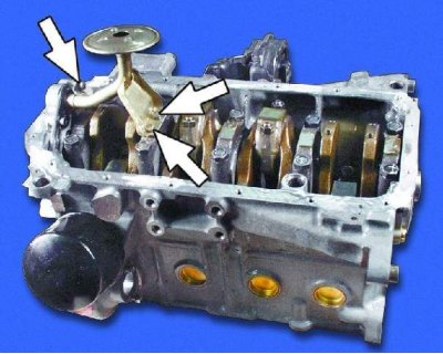
To remove the oil filter, use a special key. If you don't have a key and you can't unscrew the…


52. Unscrew the oil filter. Unscrew the two bolts securing the oil pump receiver to the crankshaft support cover and the bolt securing it to the oil pump.
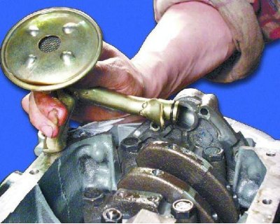
52. Unscrew the oil filter. Unscrew the two bolts securing the oil pump receiver to the crankshaft…


53. Remove the receiver tube from the oil pump and remove the receiver.
53. Remove the receiver tube from the oil pump and remove the receiver.


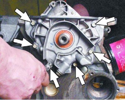
54. Remove the six oil pump mounting bolts.
54. Remove the six oil pump mounting bolts.


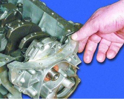
55. Remove the oil pump by sliding it off the nose of the crankshaft.
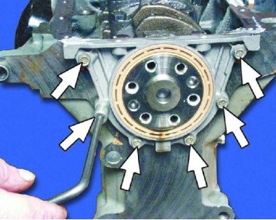
55. Remove the oil pump by sliding it off the nose of the crankshaft.


56. Remove the six bolts securing the rear oil seal holder.
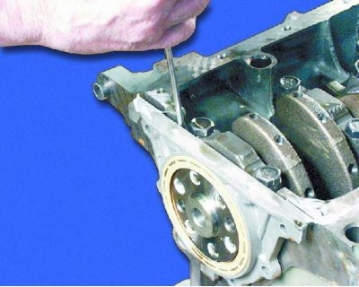
56. Remove the six bolts securing the rear oil seal holder.


57. Carefully remove the holder by pressing it away from the block with a screwdriver.
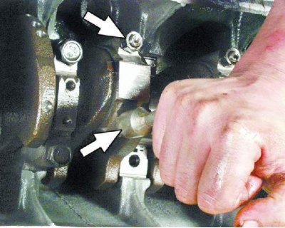
57. Carefully remove the holder by pressing it away from the block with a screwdriver.


58. Loosen the connecting rod cover fastening nuts.
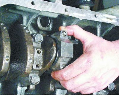
58. Loosen the connecting rod cover fastening nuts.


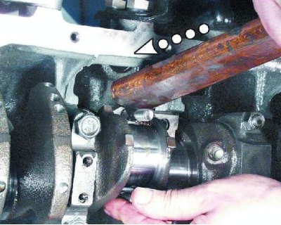
59. Remove the connecting rod cap and the bearing shell. If the cap is difficult to remove, knock it off with light hammer blows.
59. Remove the connecting rod cap and the bearing shell. If the cap is difficult to remove, knock…


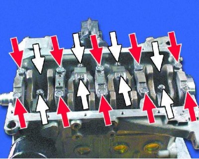
60. Push the connecting rod with the piston into the cylinder so that the connecting rod does not touch its walls. Otherwise, the cylinder wall may be damaged.
60. Push the connecting rod with the piston into the cylinder so that the connecting rod does not…


Location of connecting rod mounting nuts (white arrows) and bolts for fastening the main bearing caps (red arrows).
Location of connecting rod mounting nuts (white arrows) and bolts for fastening the main bearing…


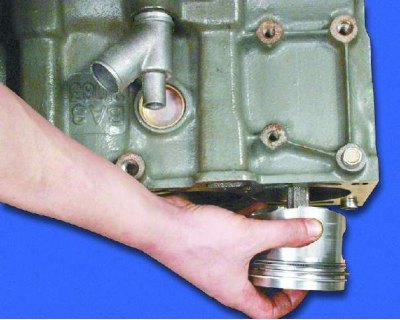
61. Carefully remove the piston assembly with the connecting rod and upper bearing from the block, being careful not to damage the cylinder bore. Remove the remaining pistons in the same manner. If the bearings remain on the shaft, remove them.
61. Carefully remove the piston assembly with the connecting rod and upper bearing from the block,…


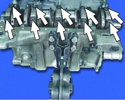
62. Loosen the main bearing cap mounting bolts.
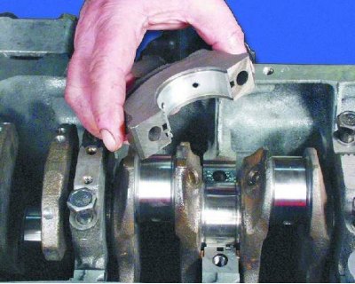
62. Loosen the main bearing cap mounting bolts.


63. Remove the main bearing caps and lower bearing shells. Remove the crankshaft from the cylinder block.
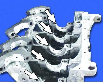
63. Remove the main bearing caps and lower bearing shells. Remove the crankshaft from the cylinder…


64. Remove the upper main bearing shells from the cylinder block beds. Remove the support half rings from the middle support.

When disassembling the engine, we recommend replacing the liners.


This article is available at russian, bulgarian, belarusian, ukrainian, serbian, croatian, romanian, polish, slovak, hungarian
The text was reviewed by the specialist: Grigory Vologodtsev

Share with friends:

Previous articles
VAZ-21099: Engine repair
Next articles

Adjusting valve clearances
Removal and installation the engine
Cylinder block — inspection, defect detection and repair
Piston with connecting rod — disassembly, defect detection and assembly
Cylinder head — design description
Disassembling the cylinder head
Inspection and defect detection of parts

More articles from other manuals on VAZ cars:
➠ Engine repair with complete disassembly VAZ-2110 (1995-2007)
➠ The structure of a car engine VAZ-1111 (1988-1996)
➠ General structure of a car engine VAZ-2101 (1970-1983)
➠ The engine structure of VAZ-2104 and VAZ-2105 cars VAZ-2105 (1979-2010)
➠ The engine structure of VAZ-2106 and VAZ-2103 cars VAZ-2106 (1976-2006)
Link in different formats to this page


Visitor comments

No comments yet


How much will 20 + 31 ?


VAZ-21099 (1990-2004) 
  • General information
  • Specifications
  • User manual
  • Maintenance
  • Car care
  • Troubleshooting
  • Power unit
  • Engine repair
  • Cooling and lubrication system
  • Power and exhaust system
  • Transmission
  • Car gearbox
  • Clutch and drive shafts
  • Chassis
  • Car suspension
  • Steering
  • Brake system
  • Body
  • Exterior
  • Interior
  • Doors and locks
  • Electrical equipment
  • Equipment and devices
  • Lighting and signaling
  • Engine electrics
  • Ignition system


VAZ-2109 (1984-1997) 
  • General information
  • Vehicle operation
  • Vehicle device
  • Power unit
  • Engine repair
  • Cooling and lubrication system
  • Supply system
  • Transmission
  • Clutch
  • Gearbox and drive
  • Chassis
  • Car suspension
  • Steering
  • Brake system
  • Body
  • Body elements
  • Electrical equipment
  • Engine electrics
  • Equipment and devices


VAZ-2108 (1984-2003) 
  • General information
  • Introduction to guide
  • Power unit
  • Engine repair
  • Cooling and lubrication system
  • Power and exhaust system
  • Transmission
  • Clutch and drive shafts
  • Car gearbox
  • Chassis
  • Front suspension
  • Rear suspension
  • Steering
  • Brake system
  • Body
  • Exterior
  • Interior
  • Doors and glass
  • Electrical equipment
  • Equipment and devices
  • Engine electrics
  • Ignition system


VAZbook.ru © 2017 · Mobile version · Contact with administration · Sitemap: EN BG BY UA RS HR RO PL SK HU · Site search · News and articles VAZ-1111 · VAZ-11113 · VAZ-2101 · VAZ-21011 · VAZ-2104 · VAZ-2105 · VAZ-21051 · VAZ-2106 · VAZ-21061 · VAZ-2107 · VAZ-21099 · VAZ-2109 · VAZ-2108 · VAZ-2110 · VAZ-2112 · VAZ-2114 · VAZ-2115 · VAZ-2121 · VAZ-21213 · VAZ-21214 ·
The site stores technical data using cookies to improve the service.