




Attention! Boring and honing of cylinders must be carried out in specialized workshops.
Note 1: Two cylinder repair sizes are provided.
First repair size: cylinder diameter increased by 0.4 mm.
Second repair size: diameter increased by 0.8 mm.
Even if defects are found in only one cylinder, it is necessary to bore all four cylinders to the same repair size.
(The article is copied from the website VAZBOOK.ru)
Note 2. There is a special device for measuring cylinders – a bore gauge.
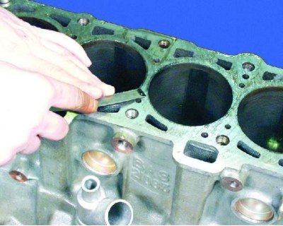
1. Carefully clean the cylinder block surfaces of any old sealing gaskets. Carefully inspect the block, especially in the areas of the holes for the cylinder head mounting bolts. If cracks appear on the block, it must be replaced.
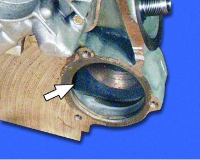
2. Check the tightness of the cylinder block cooling jacket. To do this, plug the hole under the water pump and pour kerosene into the cooling jacket. If kerosene leakage is noticeable, then the block is not tight and must be replaced.
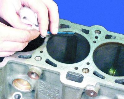
3. Inspect the cylinders. If there are scratches, burrs, cavities or other defects on the cylinder surface, bore the cylinders to the repair size (see note 1) or replace the cylinder block. If the defects are more than 0.8 mm deep, the block cannot be repaired and must be replaced. Clean the carbon deposits on the top of the cylinders. If a belt has formed there due to cylinder wear, remove it with a scraper.
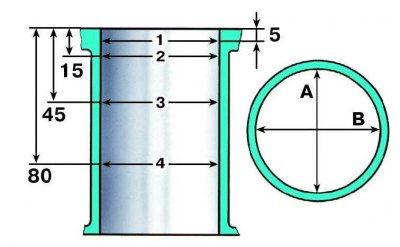
4. Measure the cylinder diameters in two perpendicular planes (along and across the cylinder block) and four belts (see note 2). If the obtained result in at least one cylinder exceeds the nominal value by more than 0.15 mm, the cylinders must be bored to the next repair size.
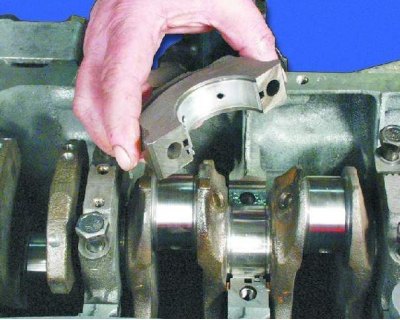
5. Check the clearances between the main bearing shells and the crankshaft journals. The nominal clearance should be within 0.026–0.073 mm. The maximum permissible clearance is 0.15 mm. If the result obtained exceeds 0.15 mm, the crankshaft must be ground to the next repair size and the liners of the corresponding repair size must be installed.
The manufacturer recommends checking the gaps using a plastic calibrated wire as follows:
- 1). Thoroughly clean the beds and covers from oil deposits.
- 2). Clean the crankshaft journals and bearing shells.
- 3). Place the crankshaft on the main bearing beds with the bearing shells installed.
- 4). Place pieces of calibrated plastic wire on the crankshaft journals.
- 5). Install the main bearing caps with the liners installed in them, tighten the cap mounting bolts and tighten to a torque of 82 N·m (8.2 kgf·m), without turning the crankshaft.
- 6). Remove the main bearing caps. The clearance is determined by the degree of flattening of the wire using the scale on the wire package.
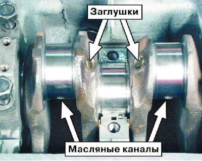
6. Thoroughly clean and flush the crankshaft oil passages. Do not press out the plugs yourself; if necessary, contact a service station.
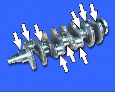
7. If there are minor burrs, scratches, or grooves on the main and connecting rod journals, or if the journal wear exceeds 0.03 mm or the journal ovality exceeds 0.03 mm, then the journals must be ground to the nearest repair size. Then polish the journals and blunt the sharp edges of the oil channel chamfers with an abrasive cone. Wash the crankshaft and blow out the oil channels with compressed air. The ovality and taper of all journals must not exceed 0.005 mm. After grinding the journals, install liners of the corresponding repair sizes. If there are cracks on the crankshaft, replace it.
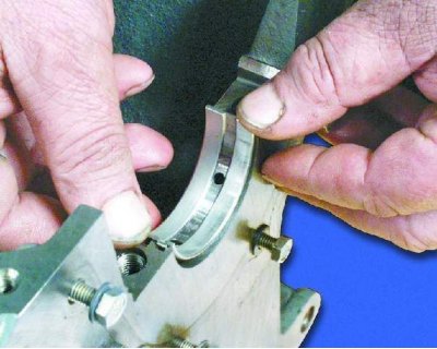
8. Inspect the main bearing shells. If there are any scratches, scoring, peeling, inclusions of hard particles, etc., replace the shells.