




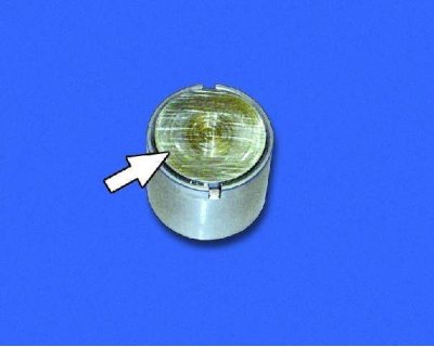
Valve lifter with adjusting washer installed.
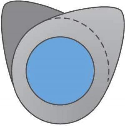
Position of the cams of the first cylinder when installing the camshaft on the cylinder head supports.
Caution: Before installing the camshaft, place wooden shims under the cylinder head to avoid damaging the valves.
Caution! The inlet pipe and outlet manifold gaskets supplied as spare parts are made of different thicknesses of material, so when installing new gaskets, make sure that their thickness is the same.
Caution! Do not tighten the spark plugs too much, as this may cause cracks in the spark plug insulator. The tightening torque of the spark plugs is 31-39 N·m (3.1-3.9 kgf·m).
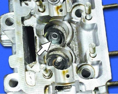
1. Install the valve spring support washer (plate).
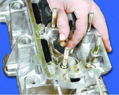
2. Press the valve stem seal onto the valve guide using a mandrel (the mandrel is not shown in the photo).
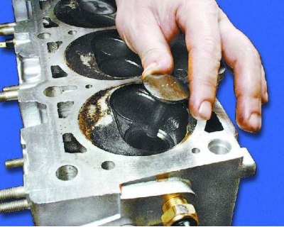
3. Lubricate the valve stem with engine oil and insert it into the guide bushing of the corresponding cylinder (according to the marks made during disassembly).
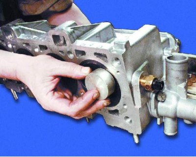 |
 |
4. Place a suitable stop under the valve.
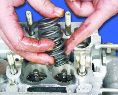
5. Turn the cylinder head over and insert the inner and outer valve springs.
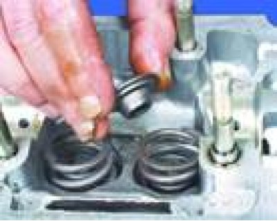
6. Install the valve spring plate onto the springs.
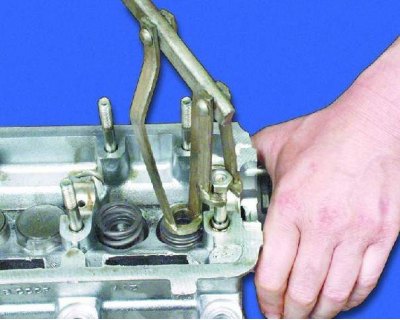
7. Install the valve spring compressor.
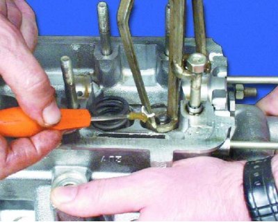
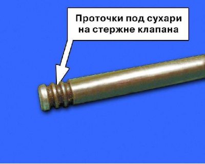
8. For ease of installation, glue the cracker to a thin screwdriver with grease. Compress the valve springs with the tool to release the cracker grooves on the valve stem. Insert the cracker into the grooves.
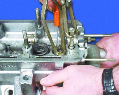
9. Insert the second cracker in the same way and, gradually loosening the pressure on the handle of the device, release the valve springs so that the crackers enter the hole in the valve spring plate. Remove the device. Install the remaining valves in the same way.
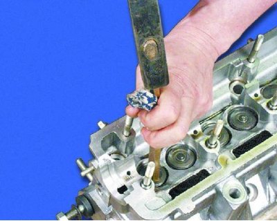
10. Tap the ends of each valve stem with a hammer through a metal rod to seat the crackers in place.
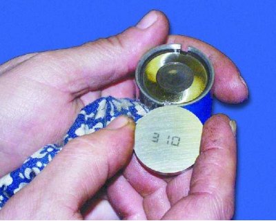
11. Insert the adjusting washers into the tappets according to the marks made during disassembly. The washers are inserted into the tappet with the side where the washer thickness value is engraved.
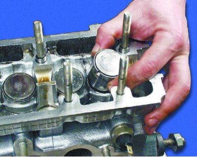
12. Lubricate with engine oil and install the tappets into the appropriate cylinders (according to the marks made during disassembly).
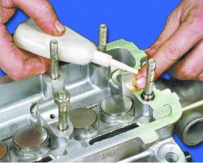
13. Lubricate the camshaft bearings in the cylinder head and the tappet adjusting washers with engine oil (see note).
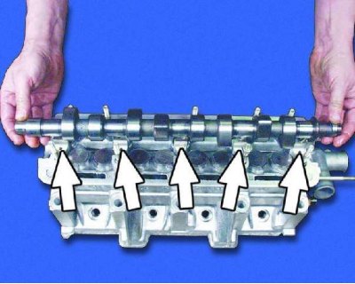
Note: Before installing the camshaft, lubricate all bearings with engine oil.
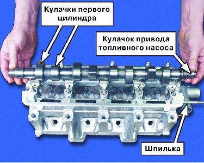
14. Install the camshaft on the supports so that both cams of the first cylinder are directed upwards. In this case, the cam of the fuel pump drive should be on the side of the ignition distributor mounting studs.
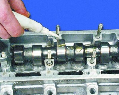
15. Lubricate the camshaft journals and cams with engine oil.
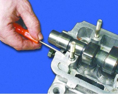
16. Apply a thin layer of sealant to the surface of the head that mates with the bearing housings in the area of the outer camshaft supports.
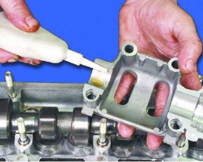
17. Lubricate the camshaft bearings in the bearing housings with engine oil.
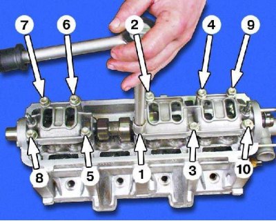
18. Install the bearing housings on the cylinder head and tighten their mounting nuts in the specified order to a torque of 18.7-23.0 N·m (1.87-2.30 kgf·m).
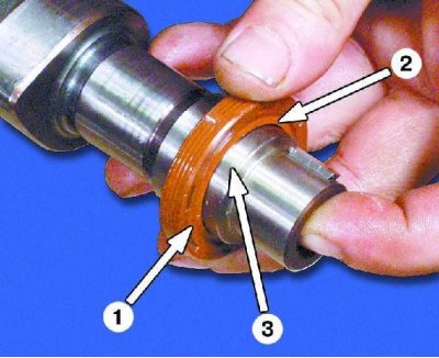
1 – outer side of the seal
2 – working edge of the seal
3 – camshaft journal
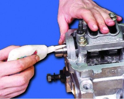
19. Lubricate the seal seat in the cylinder head and on the camshaft with engine oil.
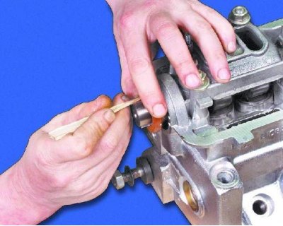
20. The camshaft seal is installed using a special mandrel. If there is no mandrel, place the seal on the camshaft up to the seat on the shaft. Then, using a pointed stick made of soft wood, carefully tuck the working edge of the seal onto the shaft journal.
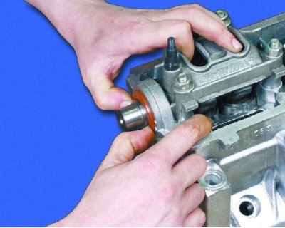
21. Carefully push the seal in until it stops.
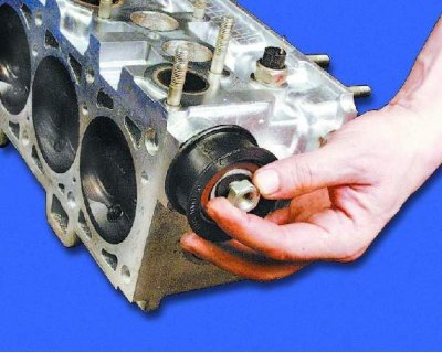
22. Install the tension roller on the stud and screw on the fastening nut without tightening it.
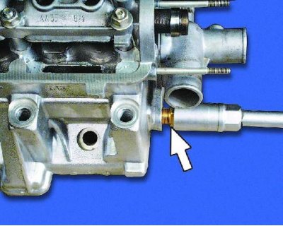
23. Reinstall the coolant temperature sensor.
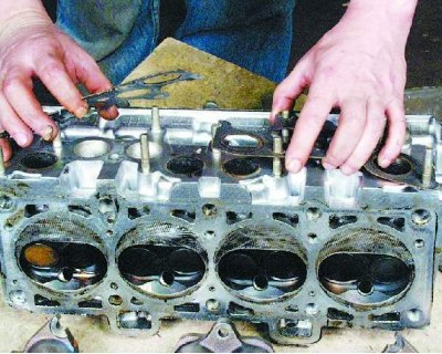
24. Install the intake manifold and exhaust manifold gaskets (see warning).
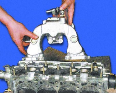
25. Install the intake pipe onto the studs.
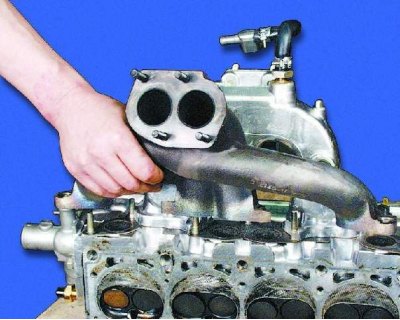
26. Install the exhaust manifold onto the studs.
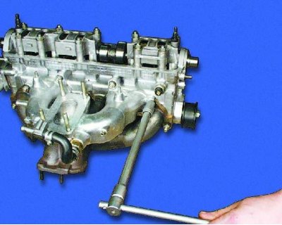
27. Tighten the nine nuts securing the intake pipe and exhaust manifold to a torque of 21-26 N·m (2.1-2.6 kgf·m).
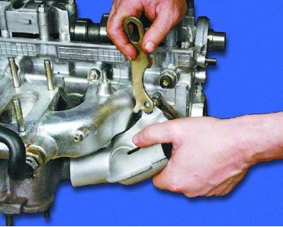
28. Install the warm air intake pipe and eye onto the studs.
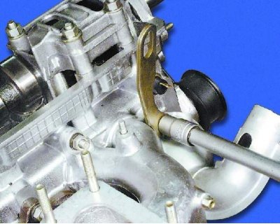
29. Tighten the nut securing the pipe and eye.
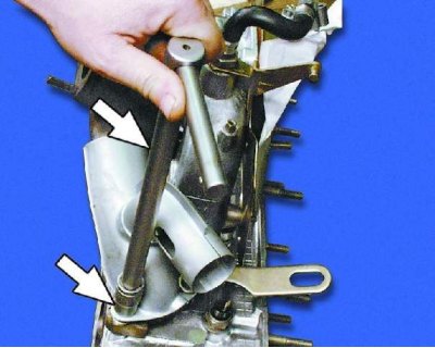
30. Tighten the two remaining nuts securing the pipe.
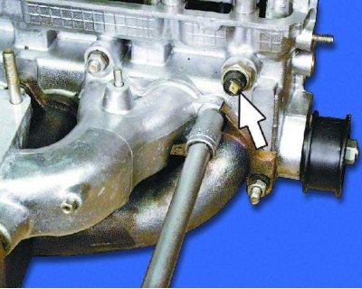
31. Screw in the oil pressure warning light sensor.
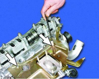
32. Install the carburetor heat shield onto the studs and tighten the two nuts that secure it.
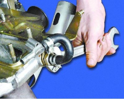
33. Tighten the shield mounting nut onto the fitting.
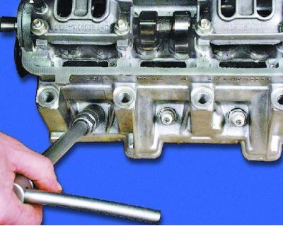
34. Tighten the spark plugs.
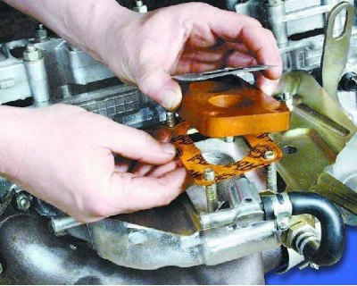
35. Install the carburetor gaskets.
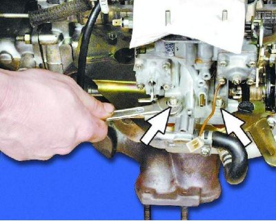
36. Install the carburetor on the studs and tighten the four nuts securing it to a torque of 13-16 N·m (1.3-1.6 kgf·m).
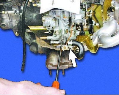
37. Tighten the screw securing the carburetor heating nipple.