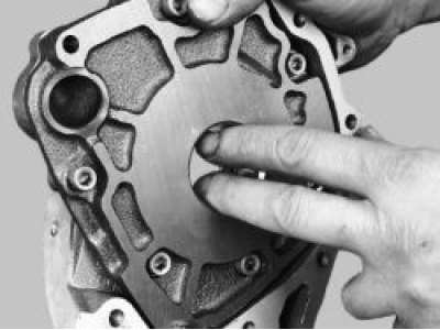
1. Remove the oil pump from the vehicle (see "Removal and installation the oil pump").
2. Remove the six pump cover mounting bolts.
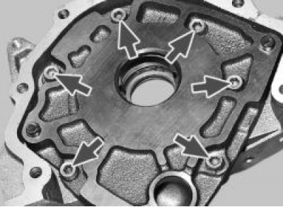
3. Using two screwdrivers, lift the pump body until the locating pins on the body come out of the holes in the pump cover and remove the pump body from the cover.
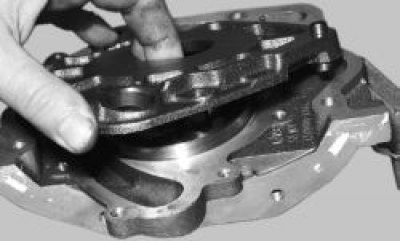
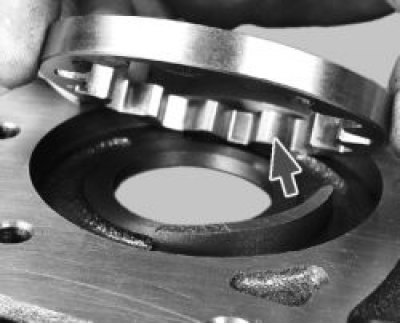
4. Remove the leading… from the lid
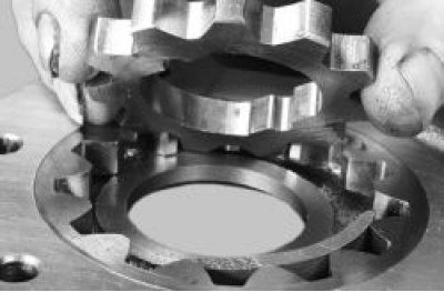
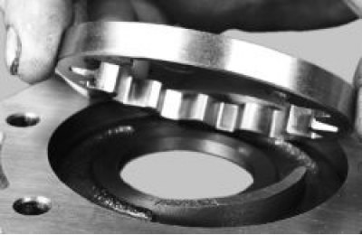
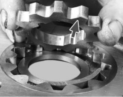
5. …and the driven gear of the pump.
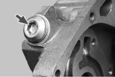
6. Unscrew the plug of the pressure reducing valve. Note: there is an aluminum sealing ring installed under the plug. Replace a ring that is too tight.
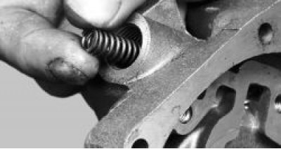
7. Remove the pressure reducing valve spring.
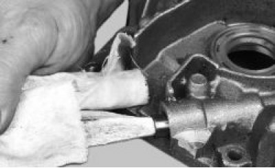
8. Remove the pressure reducing valve by gently tapping the body on a clean wooden board. If the valve does not come out, remove it with a sharp wooden stick.
9. Inspect the aluminum cover. There should be no visible signs of wear, burrs or deep scratches in the area where the gears meet. Otherwise, replace the cover.
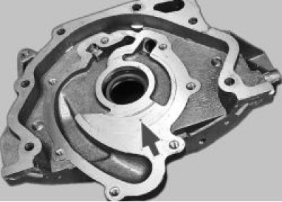
10. Inspect the pump body. There should be no visible signs of wear, burrs or deep scratches on its working surfaces. Otherwise, replace the body.
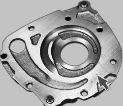
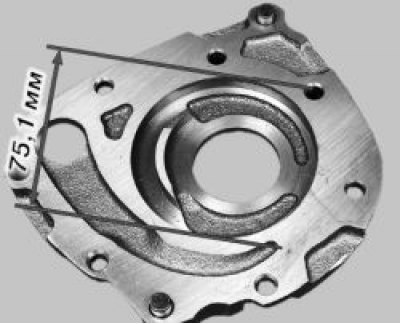
11. Measure the diameter of the driven gear seat on the pump housing. The maximum allowable diameter is 75.1 mm. If the size exceeds the specified one, replace the housing.
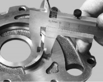
12. Measure the width of the pump housing segment in the middle. If the width is less than 3.4 mm, replace the housing.
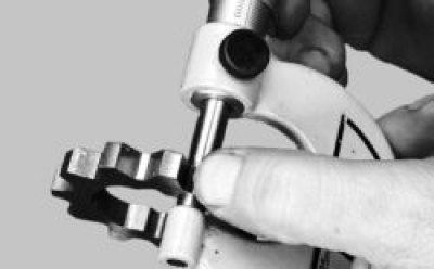
13. Measure the thickness of the pinion gear. If it is less than 7.42 mm, replace the pinion gear.
The information is posted on the portal (VAZBOOK.ru)
14. Measure the thickness of the driven gear. If it is less than 7.35 mm, replace the gear.
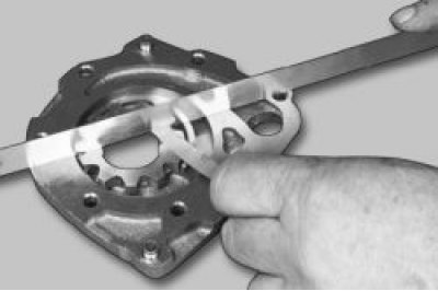
15. Check the axial clearances of the gears. To do this, install the drive gear in the housing, place a metal ruler on the housing and measure the clearance between the ruler and the gear with a feeler gauge.
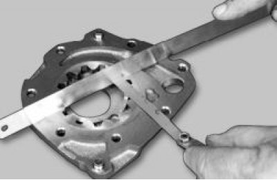
16. Measure the axial clearance of the driven gear in the same way. The maximum permissible axial clearance for the driving gear is 0.12 mm, for the driven gear – 0.15 mm. If the clearances exceed the specified ones, replace the gears.
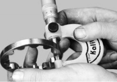
17. More accurate axial clearances of gears can be obtained by calculation. To do this, measure the thickness of the housing on the outer surfaces with a micrometer..
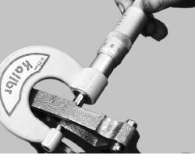
18. …and the thickness of the housing in the area of the gear socket in several places (on milled surfaces). Calculate the axial clearance as the difference between the arithmetic mean of the nest depth and the thickness of the gears.
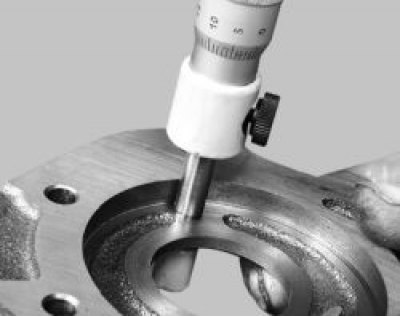
19. Inspect the relief valve seat. There should be no burrs or deep scratches on its inner surface. Otherwise, replace the cover.
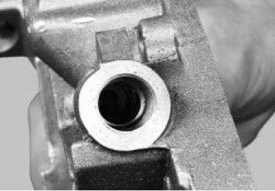
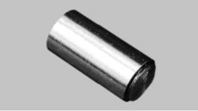
20. Replace the pressure relief valve if it has burrs or deep scratches.
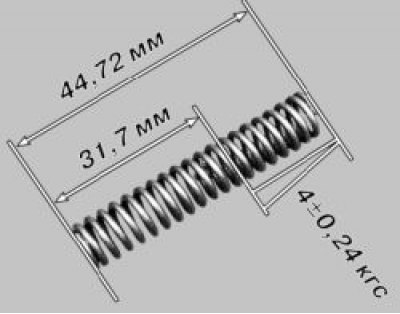
21. Replace the bent, broken or cracked pressure reducing valve spring. The height of the spring in a free state should be 44.72 mm, under a load of (4±0.24) kgf – 31.7 mm. Otherwise, replace the spring.
22. Install the driven gear into the pump housing. The chamfers on the gear teeth should face the housing.
23. Install the drive gear into the pump housing. The chamfers on the gear teeth should face the housing.
24. Install the cover on the body and screw in the bolts that secure it.
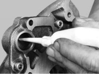
25. Lubricate the pressure reducing valve with engine oil and install it in the seat with the bottom down. Then install the spring and screw in the plug with the sealing ring.
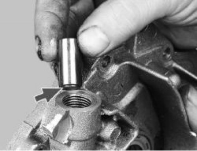
26. Fill the pump with engine oil through the hole under the oil receiver.
27. Turn the pump gears a few revolutions to lubricate their working surfaces.