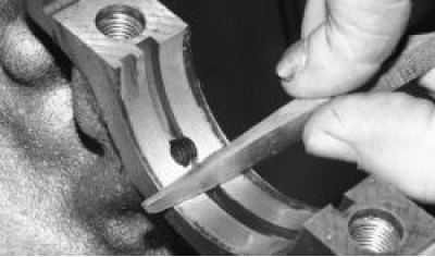
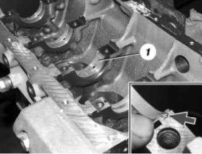
2. Install the main bearing shells in the cylinder block bed in accordance with the marks made during disassembly. Note that the middle shell 1 is without a groove. When installing the shells, their locking tabs must enter the grooves of the beds. Lubricate the shells with engine oil.
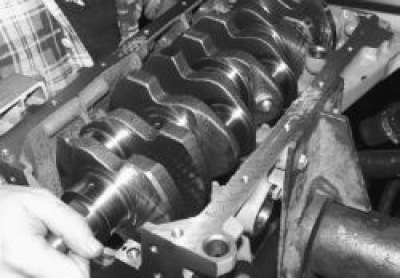
3. Install the crankshaft into the cylinder block.
4. Lubricate the thrust half rings with engine oil. Pay attention to the grooves of the half rings - these sides of the half rings are installed to the crankshaft cheeks.
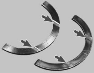
5. Install the steel-aluminum half ring (white color) from the front side of the middle bed (from the camshaft drive side)…
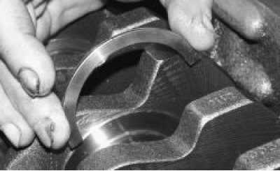
6. …metal-ceramic (yellow color) - on the other side of the bed.
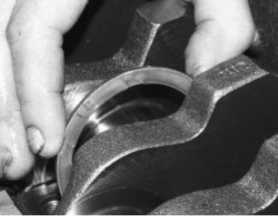
7. Rotate the half rings so that their ends are flush with the ends of the bed.
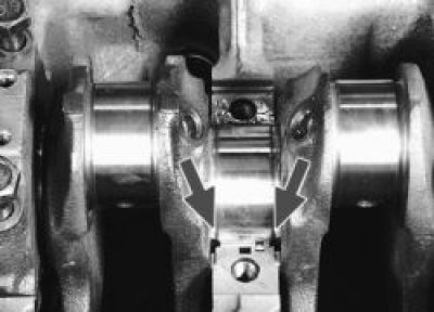
8. Insert the liners into the main bearing caps in accordance with the marks made during disassembly. The locking tabs of the liners should enter the grooves of the caps. Lubricate the liners with engine oil.
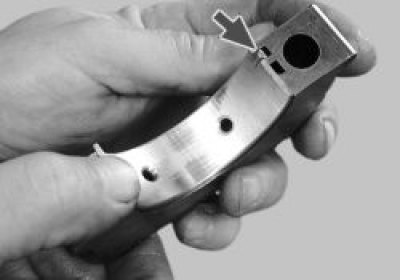
9. Install the caps according to the marks. The caps have marks (notches) according to the cylinder number. The exception is the fifth cap, which has two marks, like the second one. The second cap has two threaded holes for the oil receiver mounting bolts. The cylinder numbers are counted from the camshaft drive side, and the caps are installed with marks 1 towards the generator bracket 2.
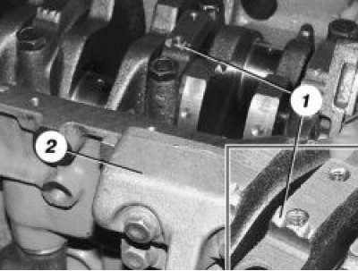
10. Lubricate the threads and ends of the heads of the cover mounting bolts with engine oil.
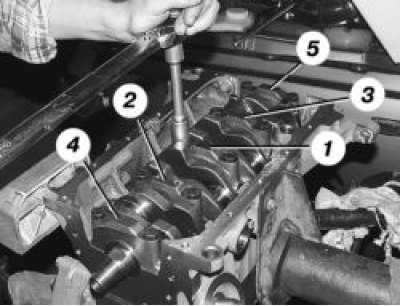
11. Screw in the bolts and tighten them to the required torque (see "Tightening torques") in the following order: first tighten the bolts of the third cover 1, then the second 2 and the fourth 3, then the first 4 and the fifth 5. After tightening the bolts, turn the crankshaft two or three turns - it should rotate easily, without jamming.
12. For ease of installation, apply a thin layer of grease to the oil pump gasket and "glue" it to the block. Remove excess grease.
13. Install the oil pump and screw in its mounting bolts (see "Removal and installation the oil pump").
14. For ease of installation, apply a thin layer of grease to the rear oil seal retainer gasket and "glue" it to the block. Remove excess grease.
15. Install the rear oil seal holder and screw in the bolts for securing it (see "Replacing crankshaft seals").
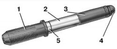
4.16. Device for pressing in the piston pin: 1 – roller; 2 – piston pin; 3 – guide bushing; 4 – screw; 5 – distance ring
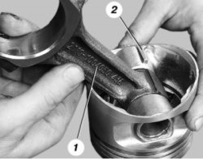
16. Insert the connecting rod into the piston in accordance with the previously made marks so that part number 1 on the connecting rod faces the opposite direction from the lug 2 on the piston boss.
17. It is better to use a special device to press in the piston pin. If you don't have one, you can select a suitable mandrel. Put the piston pin 2 (Fig. 4.16) on the shaft 1 of the device for installing the piston pin with the spacer ring 5 put on it. Then put on the guide sleeve 3 and secure it with screw 4, without tightening it. Dimensions of the spacer ring: outer diameter 22 mm, inner – 15 mm, thickness – 4 mm.
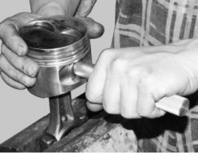
18. Heat the upper connecting rod head to 240°C in an oven for 15 minutes. Clamp the connecting rod in a vice, install the piston on it so that the holes for the pin match, and insert the device with the pin into the holes of the piston and connecting rod until it stops. For correct installation of the pin, the piston must be pressed with the boss against the upper connecting rod head in the direction of pressing.
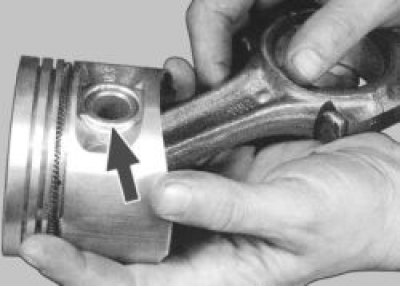
19. After the connecting rod has cooled, lubricate the piston pin through the hole in the piston bosses.
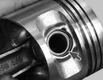
20. Install the retaining rings on both sides of the pin. Make sure that the rings are firmly seated in the piston grooves.
21. Install the oil scraper ring expansion spring onto the piston.
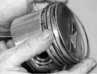
22. Install the piston rings. It is recommended to do this with a special puller. If you do not have one, install the rings on the piston, carefully spreading their locks.
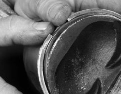
23. Ring installation order: the oil scraper ring is installed first (the ring lock must be on the opposite side of the release spring lock), then the lower compression ring, and lastly the upper one.
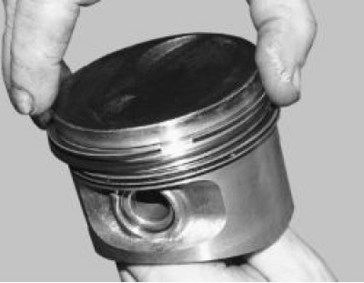
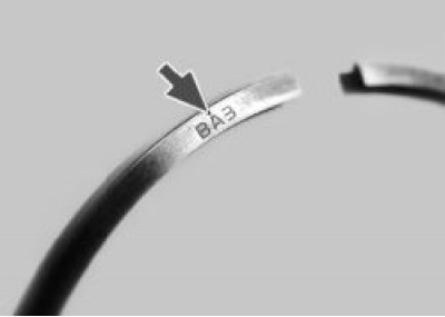
24. Please note that the rings may have the inscription "VAZ", "TOP" or "TOP" stamped on them. The rings are installed with this inscription facing up (to the piston bottom). If there is no inscription, the oil scraper and upper compression valves can be installed in any position.
(The source is on the website: «VAZBOOK.RU»)
25. The lower compression ring differs from the upper one, in addition to thickness, by the presence of a groove; it is installed with this groove facing down.
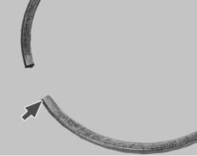
Turn the rings in the piston grooves to make sure they rotate easily. If any ring does not rotate or is sticking, it must be replaced.
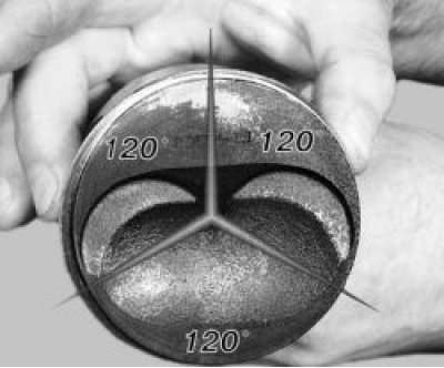
26. Install the rings on the piston so that their locks are located at an angle of 120° to each other.
27. Carefully wipe the crankshaft connecting rod journals with a clean cloth.
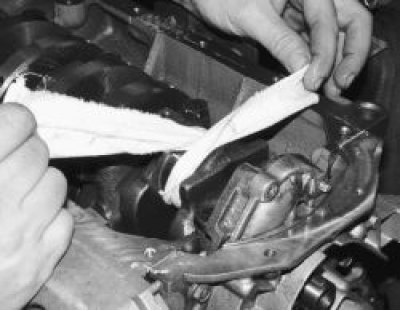
28. Carefully wipe the cylinder mirrors with a clean cloth and lubricate them with engine oil.
29. Insert the bearing into the connecting rod in accordance with the previously made marks so that the bearing pin fits into the groove in the connecting rod. After this, lubricate the bearing and piston with engine oil.
30. Place a special mandrel on the piston to compress the piston rings and carefully lower the connecting rod into the cylinder. It is recommended to first turn the crankshaft so that the piston being installed is at BDC. The arrow on the piston bottom should point toward the front of the engine (towards the camshaft drive).
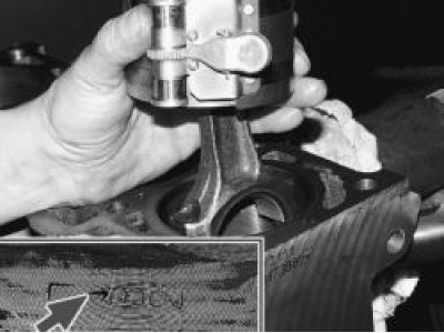
31. Press the mandrel firmly against the block and use the hammer handle to push the piston into the cylinder. If the mandrel does not fit tightly against the cylinder block, the piston rings may break.
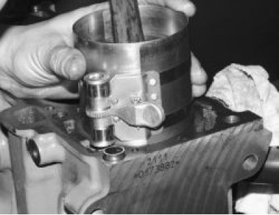
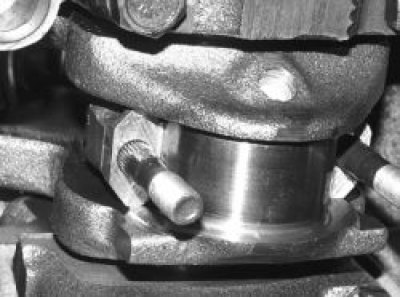
32. Install the lower connecting rod head onto the crankshaft journal.
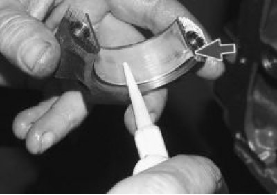
33. Insert the bearing into the connecting rod cap in accordance with the previously made marks so that the bearing tab enters the groove in the cap. After this, lubricate the bearing with engine oil.
34. Install the connecting rod cap. The cylinder numbers on the cap and the connecting rod lower head must be on the same side.
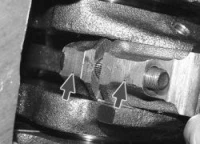
35. Tighten the cover mounting nuts to the specified torque (see "Tightening torques"). Install the remaining pistons in the same way.
36. Insert the oil level sensor into the cylinder block. If necessary, turn the crankshaft so that the shaft counterweight does not interfere with inserting the sensor. Then tighten the sensor mounting bolt.
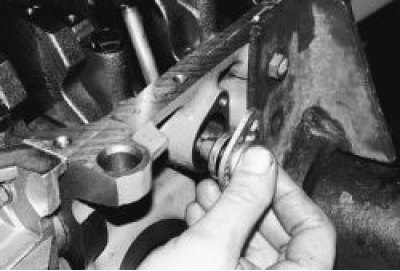
37. Install the oil receiver and screw in the three bolts that secure it.
38. Apply sealant to the flywheel mounting bolts. Install the flywheel, lock plate and screw in the flywheel mounting bolts (for details, see. "Removal, installation and inspection of the flywheel").
39. For ease of installation, apply a thin layer of consistent grease to the surface of the block and "glue" the oil pan gasket to it.
40. Install the oil pan and screw in its mounting bolts (see "Tightening torques"). Next, assemble the engine in the reverse order of disassembly. Install the cylinder head (see "Replacing the cylinder head gasket" in the subsection "Replacing engine sealing parts"), the camshaft drive belt (see "Replacing the camshaft drive belt and adjusting the belt tension").
41. Install the remaining components and parts in the reverse order of removal.
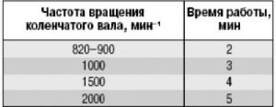
Helpful tips: After assembling the engine, it is recommended to run it in on a stand. Since this cannot be done outside of special repair organizations, after installing the engine on the car, run it in using a simplified cycle:
- make sure the throttle actuator is adjusted correctly, fill with oil and coolant, check the tightness of all connections;
- start the engine and let it run without load for the next cycle.
- Do not operate the engine at maximum speed;
- during operation, check the tightness of the engine and its systems, oil pressure, pay attention to the presence of extraneous noises;
- if any extraneous noise or other malfunctions are detected, stop the engine and eliminate the cause;
- once you start using your vehicle, follow the procedures provided for the break-in period of a new vehicle.