
Removal and installation
The pipelines are disconnected from the regulator by unscrewing the nuts securing it to the mudguard rack of the body, and the pressure regulator is removed. When disconnecting pipelines, pay attention to their position in order to connect them to the same sockets during installation. Interchange of pipelines is unacceptable.
Installation of the pressure regulator is carried out in the reverse order.
Disassembly, Parts Inspection and Assembly
Depending on the nature of the malfunction, disassembly of the pressure regulator may be complete or incomplete. In case of fluid leakage from under the plug, the regulator is not completely disassembled. To do this, unscrew the plug 1 (see fig. 119), take out the spring 2 with the support cup and, supplying compressed air to the chamber C, push the pusher 19 complete with sealing rings 5 and bushing 4 out of the housing.
Complete disassembly is carried out in case of leakage of brake fluid from under glass 12 or inconsistency in the characteristics of the pressure regulator when tested on the stand. With a complete disassembly with a 2.5-3 mm drill, the points of punching of the glass 12 are drilled out, while being careful not to damage the regulator housing. Glass 12 is pressed with a special device and removed complete with spring 11, stops 8, 9 and cap 10. Then the retaining ring 7 is removed, having previously pressed the sleeve 13 into the housing. Holding sleeve 13 on the piston rod, the piston 14 is removed complete with seal 6, spring, washers, sealing ring 15 and sleeve 13. Sleeve 17 is locked in the housing by ring 16 and cannot be removed from the housing.
Plug 1 is unscrewed and spring 2 and pusher 19 are assembled with plate, ring 18, o-rings 5 and bushing 4 from the housing.
Check the spring 11. Its length should be 24 mm under load (110±11) N.
Checking details
Wash the parts with isopropyl alcohol or brake fluid and inspect them carefully. The surfaces of the parts must not be damaged or noticeably worn. Check the condition and elasticity of the pusher bushing spring. Its length should be 7.5 mm under load (14±1,5) H. Damaged and worn parts, as well as o-rings, are replaced with new ones.
At the stand BS-137.000, the tightness of the pressure regulator valve, rolled in plug 1, is checked. If it leaks liquid, the regulator plug assembly with the valve is replaced.
Assembly
Assemble the pusher assembly, lubricating all parts with brake fluid. The assembled assembly is installed in the pressure regulator housing, a cup with a spring is installed and the plug is tightened with 1 torque (39,2—49) N·m
The sinking of plug 3 in the regulator body is checked, which should be 1-2 mm. When assembling, glass 1 is replaced with a new one.
Checking the pressure regulator on the bench
Having installed the pressure regulator on the stand, connect it as shown in fig. 129.
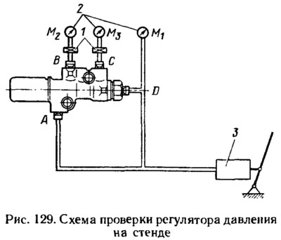
Bleed the system through valves 1.
Check the tightness of the connection of the regulator to the stand (leakage of brake fluid is not allowed) .
A pulsating pressure of 0-8 MPa with a frequency of about 1 Hz is supplied to the inputs A and D of the regulator. Perform 15-20 cycles for running-in parts of the regulator. The pressure is generated by cylinder 3.
Determine the turn-on pressure of the regulator. To do this, use manometers 2 (M1 them2). Slowly applying pressure to inputs A and D, measure the pressure at which a difference appears between their readings. Pressure gauge M1 will increase at the same rate, and the rate of pressure increase on the pressure gauge M2 decreases, and its readings will lag behind. The pressure at which the difference in the readings of the manometers begins to appear corresponds to the switch-on pressure of the regulator. It should be (3,5±0,5) MPa.
Check the operation of the pressure regulator in the range of 3-12 MPa at the inlets A and D. The pressure at the outlet B (pressure gauge reading M2) must fit within the shaded area (pic. 130).
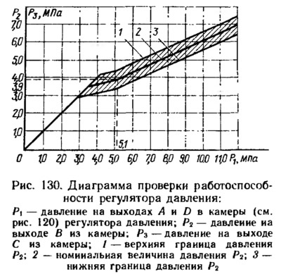
Manometer readings M3 them2 (see fig. 129) should not differ by more than 0.5 MPa in the range from 0 to 12 MPa at the inputs A and D of the regulator.