
Removal and installation
Raise the rear of the car and remove the wheel and hub cap. Remove the brake drum by unpinning and unscrewing the nut securing the wheel hub bearings. After loosening the parking brake cable, disconnect from the lever 10 (see fig. 121) tip 11 of the cable, remove the spring 12, the lower coupling spring and the leaf spring 1. The brake shoes 2 are removed as an assembly with the expansion bar and the upper coupling spring, for which the lower ends of the brake shoes are first disengaged from the support. Disconnect the expander plate and the upper coupling spring from the shoes. Unscrew the nut of the bolt connecting the lever 10 of the manual drive of the shoes with the shoe.
Having taken measures to prevent leakage of fluid from the main cylinder, disconnect from the wheel cylinder 14 (pic. 134) tube for supplying brake fluid and plug the inlets of the cylinder and tube. The wheel cylinder 14 is removed. When replacing the brake shield 16, the bolts of its fastening to the axle flange 15 of the rear wheel hub are unscrewed and the shield is removed.
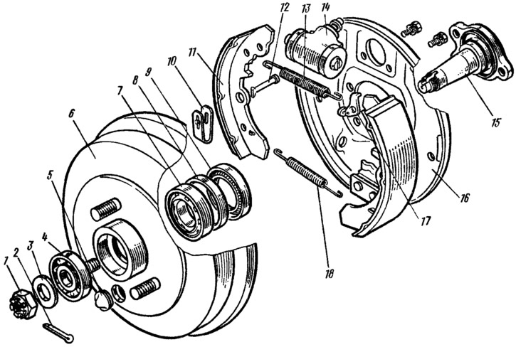
Pic. 134. Details of the brake mechanism and rear wheel axle: 1 - nut; 2 - cotter pin; 3 - washer; 4 - front bearing; 5 - plug; 6 - drum with wheel hub; 7 - rear wheel bearing; 8 — a remote ring of an epiploon; 9 - stuffing box; 10 - leaf spring; 11 - brake shoe; 12 - rack pads; 13 - upper coupling spring pads; 14 - wheel cylinder; 15 — an axis of a nave of a back wheel; 16 - brake shield; 17 - spring hook; 18 - the lower coupling spring of the pads.
The installation of the parts of the brake mechanism is carried out in the reverse order of removal, taking into account the following: after installing the pads on the brake shield, make sure that the ends of the pads are correctly positioned in the grooves of the stops of the wheel cylinder pistons and on the base plate.
Disassembly and assembly of wheel cylinders
Remove protective caps 1 (pic. 135) and pistons 2, take out seals 3, cups 9 with spring 4, unscrew fitting 7 with sealing ring 8 and cap 6. Check the cleanliness of the working surfaces of cylinder 5 and pistons. Surfaces must be perfectly smooth, without scratches or roughness, so that fluid leakage and premature wear of pistons and seals does not occur. Defects on the cylinder mirror are eliminated by lapping or grinding. However, an increase in the inner diameter is not allowed.
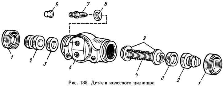
Check the elasticity of the spring. Its length in the free state should be 34 mm, under load (35±2) H—17.8 mm. If necessary, replace it. Replace seals with new ones. Also check that the protective caps of the cylinder are not damaged, if necessary, replace them with new ones.
Before assembly, liberally lubricate all parts with brake fluid. In the sequence shown in Fig. 135, install parts in the cylinder body without force, so as not to damage the rubbing surfaces. Install protective caps, then check the movement of the pistons. which should be smooth, without jamming.
Checking the technical condition of parts
Pads
Carefully check for damage or deformation on the pads. Check the elasticity of the coupling and leaf springs of the shoes, if necessary, replace them with new ones. Upper return spring must be 99 mm long under load (202,9±19,6) H, lower - 90 mm under load (134±13) N. Check the frequency of overlays; if dirt or traces of grease are found, the linings are thoroughly cleaned with a brush and washed with white spirit; in addition, check if there is any leakage of lubricant inside the drum; faults found are corrected.
The pads are replaced with new ones if the thickness of the pads has become less than 1.5 mm. The replacement is carried out simultaneously on both brake mechanisms, that is, both pairs of pads are replaced.
Brake drums
Inspect brake drums. If there are deep risks or excessive ovality on the working surface, then the drums are bored on the machine. Then the drums are ground on the machine with abrasive fine-grained bars. This increases the durability of the linings and improves braking uniformity and efficiency. Drum diameter increase (180 mm) after grinding, up to 181 mm is allowed. The maximum permissible drum diameter is 181.5 mm. These requirements must be strictly observed, otherwise the strength of the drum is violated.
Checking the wheel cylinders of the rear brakes on the stand
Install the cylinder on the stand, attach the pipeline from the pressure gauges to it (pic. 136) and pump the system. Stops 1 are adjusted so that the pistons of the wheel cylinder rest against them. Check for fluid leakage. A low-pressure pressure gauge 4 is connected and, slowly rotating the flywheel 8, the liquid pressure is set to 0.05 MPa using the pressure gauge.
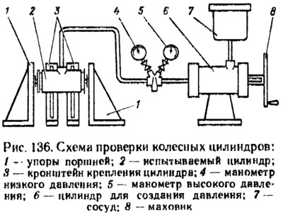
Verify that the set pressure is maintained for 5 minutes. Repeat a similar test at a pressure of 0.1-0.2-0.3-0.4-0.5 MPa.
Reduce pressure and connect high pressure manometer 5. Adhering to these rules, repeat the test at a pressure of 5-10-15 MPa. It is not allowed to reduce pressure due to fluid leakage through the sealing elements, pipeline connections, hydraulic drive bleeder or through the pores of the casting. Minor (no more than 0.5 MPa) within 5 minutes pressure reduction, especially at higher pressures, due to shrinkage of the seals.