
Removal and installation
Disconnect the elastic lever 10 (see fig. 106) the pressure regulator drive from the rear suspension lever, for which the retaining ring 14, the washer 13, and then the earring 11 are removed from the pin 15. The pipelines are disconnected from the pressure regulator, preventing leakage of brake fluid. When disconnecting pipelines, pay attention to their position in order to connect them to the same sockets during installation. Interchange of pipelines is unacceptable. Unscrew the nuts securing the bracket 9 of the pressure regulator to the bracket 8 of the body and remove the bracket assembly with the pressure regulator and its drive levers.
Installation of the pressure regulator is carried out in the reverse order.
Checking and adjusting the pressure regulator drive
Place the vehicle on a lift or inspection ditch. The car must be on wheels, be in running order. The tank should be about half full. If there is less than half of the fuel, then compensate for the missing part of the fuel with weights, placing them in the trunk.
Press the rear of the car, applying 2-3 times a force of 40-50 kgf, directed from top to bottom on the rear bumper of the car, to set the rear suspension to the middle position.
Install between the rear suspension arms and the body of the wing bar (pic. 116 - right) to fix it in this position.
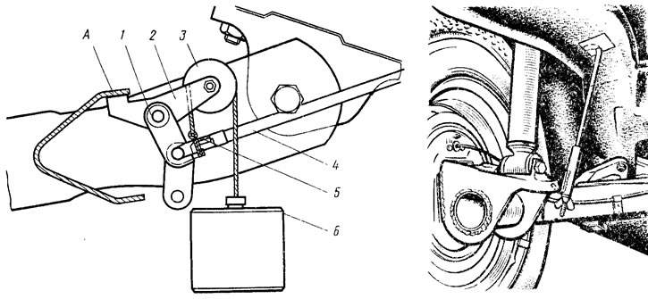
Pic. 116. Adjusting the drive of the pressure regulator
A preliminary assessment of the pressure regulator drive setting can be determined by the gap between the lower part of the lever 5 (see fig. 106) pressure regulator drive and spring 7. The gap should be within 2.0-2.1 mm.
The pressure regulator drive is adjusted using a special tool, for which:
- disconnect the earring 11 from the pin of the rear suspension arm bracket and lower the earring down. Install on the axis of the rear suspension arm bracket fixture (see fig. 116) to adjust the drive of the pressure regulator to a position in which stop A of the lever 2 of the device rests against the connector shelf of the rear suspension arms;
- the grip of the load cable 6 is hooked on the bracket 5, and the cable is thrown over the roller 3 and, slightly pressing the load down with a force of approximately 0.5 kgf, the load is lowered (its mass must be (1,5±0,05) kg);
- make sure that lever 4 does not touch the rear suspension arm;
- install the template on the axle of the rear suspension lever and check whether the template enters the groove, the lever 4 of the pressure regulator drive. This indicates the correct adjustment of the drive, in which the distance between the center of the axis of the rear suspension arm bracket and the axis of the arm 4 is equal to (28±0,2) mm.
In case of incorrect adjustment of the drive, loosen the bolts 16 and 2 (see fig. 106) pressure regulator fasteners are inserted into holes A and B of the auxiliary lever pins and move the bracket to the side until the lever 10 of the pressure regulator drive enters the groove of the template. In this position, tighten the bolts 16 and 2 for fastening the pressure regulator and, after making sure that the adjustment is correct, connect the earring 11 to the rear suspension arm bracket.
Disassembly, Parts Inspection and Assembly
Disassembly
Unscrew bolts 16 and 2 (see fig. 106) fixing the regulator and disconnect it from the bracket 9. Having unscrewed the plug 16 (see fig. 107), remove the gasket 15, take out the spring 12 and the support plate 11. Remove the protective cap 3, press on the sleeve 5 of the piston, sliding it inside the housing. Holding the piston sleeve in this position, remove the retaining ring 4. Hold the sleeve 5 until it comes out of the housing due to the force of the spring 6, remove it. Piston 2 is taken out with seals 23 and 21, washers 22, spring 6. Pusher 20 is taken out with sealing rings 10, bushing 19 and washer 9. If necessary, bushing 7 is removed from the housing with a special puller.
Checking details
Wash the parts with isopropyl alcohol or brake fluid and inspect them carefully. The surfaces of the parts must not be damaged or noticeably worn. Check the condition and elasticity of the pusher bushing spring. Its length in the free state should be 13.3 mm, under load (1,4±0,15) kgf - 7.5 mm. Damaged and worn parts, as well as sealing rings, are replaced with new ones.
At the stand BS-134.000, the tightness of the pressure regulator valve, rolled in the plug 16, is checked (see fig. 107). If it leaks liquid (damaged ring 13), replace the regulator plug assembly with the valve.
Assembly
Bushing 7 is installed if it was removed, piston 2 is assembled together with seals 21 and 23, washers 22, spring 6, bushing 5 and inserted into regulator body 1. By pressing on the sleeve 5, they shift it inside the body, insert the retaining ring 4. Lubricate the end of the sleeve 5 and the protruding part of the piston with DT-1 grease. Cap 3 is put on. Pusher 20 is assembled together with washer 9, sealing rings 10, sleeve 19, support plate 11 and inserted into the regulator body. Install the spring 12, the gasket 15 and wrap the plug 16 with a torque of 4-5 kgf-m.
If plug 24 has been lost, install a new one so that it sinks into the regulator body by 1-2 mm. During assembly, all parts are lubricated with brake fluid.
Checking the pressure regulator on the bench
Mount the pressure regulator on the stand and connect it as shown in fig. 117. Fix the end of the elastic lever in the loading device 3. Pump the system through the valves 1. Check the tightness of the connection of the regulator to the stand (no leaks allowed). Adjust the tension of the elastic arm with a load device: the switching point must be (30±1) kgf/cm2. The definition of the switching point is described in Sec. «Pressure Regulator Actuator Adjustment». Pressure gauges are used to determine the switch-on point 2 (M1 them2). A pulsating pressure of 0–80 kgf/cm is supplied through cylinder 4 to the inputs of the regulator A and G2 with a frequency of about 1 Hz. Perform 15-20 cycles for running-in parts of the regulator. Then a pressure of 80 kgf/cm is applied to the inputs A and G2. Pressure gauge reading M2 should be 42+3-5 kgf/cm2.
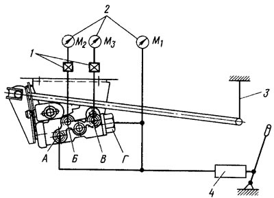
Pic. 117. Scheme for checking the pressure regulator on the stand
Check the operation of the pressure regulator in the pressure range at the inlets A and D 30-100 kgf/cm2. Outlet pressure B (pressure gauge reading M2) must fit within the shaded area (pic. 118). Manometer readings M1 them2 should not differ by more than 4 kgf/cm2 in the pressure range at the regulator inlets from 0 to 100 kgf/cm2.
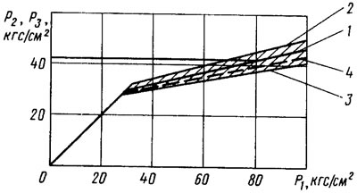
Pic. 118. Chart for checking the performance of the pressure regulator: P1 - pressure at inlets A and G (see fig. 117) pressure regulator; R2 - outlet pressure B; R3 - outlet pressure B; 1 - nominal pressure P2; 2 - upper limit of pressure Р2; 3 - lower limit of pressure P2; 4 - pressure P3