




- key "8"
- screwdriver
- electric soldering iron
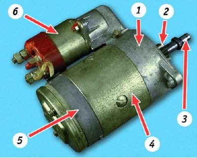
Starter: 1 - drive side cover; 2 - drive gear; 3 - anchor shaft; 4 - body; 5 - cover from the collector side; 6 - traction relay
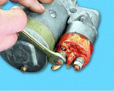
1. Loosen the nut of the lower contact bolt of the starter solenoid relay...
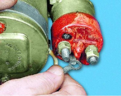
2....remove the washer and disconnect the stator winding terminal tip.
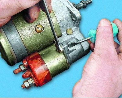
3. Unscrew the two nuts securing the starter traction relay (one is shown).
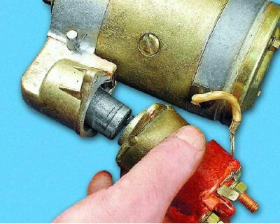
4. Remove the traction relay from the drive side cover.
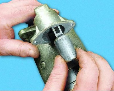
5. Remove the traction relay anchor from the drive side cover by disengaging it from the drive lever.
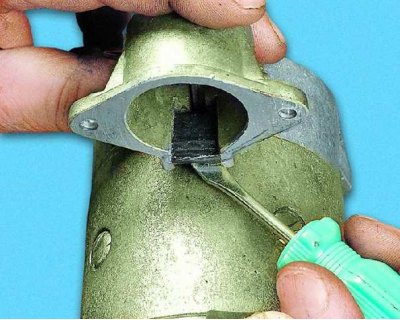
6. Remove the drive lever stop by prying it off with a screwdriver.
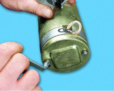
7. Loosen the two tie bolts and...
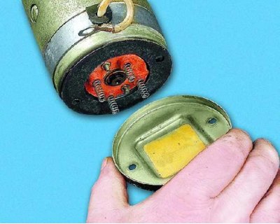
8....remove the cover from the manifold side.
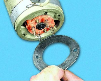
9. Remove the housing sealing gasket.
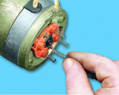
10. Remove the brush springs from the brush holder.
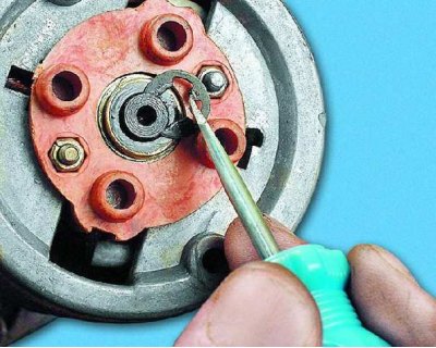
11. Remove the lock washer from the starter armature shaft and...
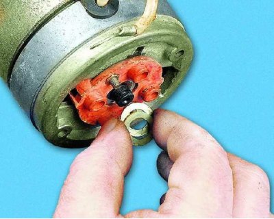
12....adjusting washers.
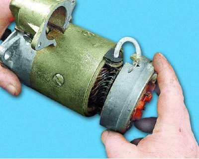
13. Disconnect the starter housing and the cover from the manifold side (if you can't do it with your hands, use a screwdriver).
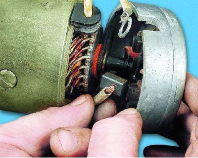
14. Remove the insulated brushes from the brush holder and...
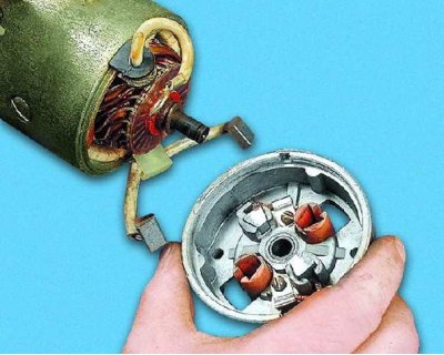
15....remove the starter cover from the manifold side.
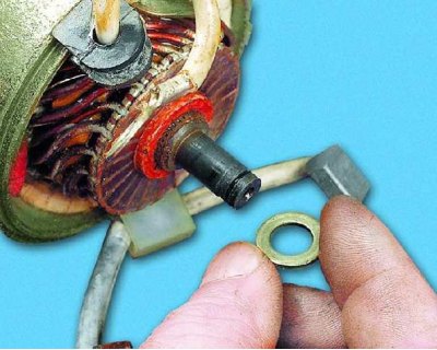
16. Remove the spacer washer from the armature shaft.
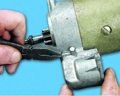
17. Remove the cotter pin securing the starter drive lever axle and...
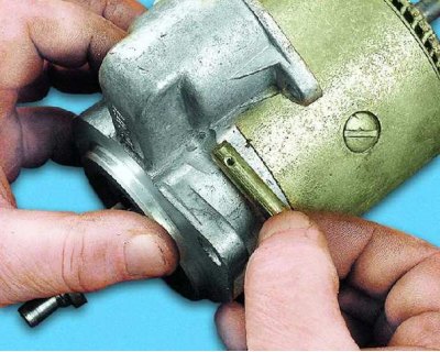
18....remove the axle from the drive side cover.
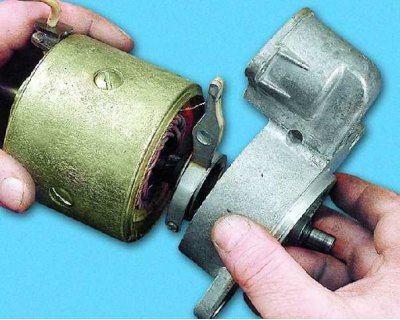
19. Remove the cover from the drive side.
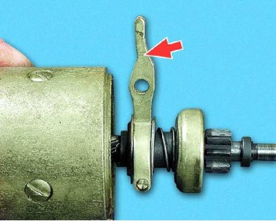
20. Remove the starter drive lever.
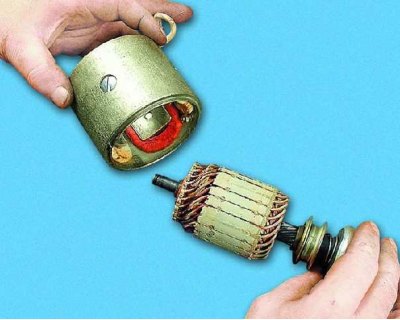
21. Remove the starter armature from the housing.
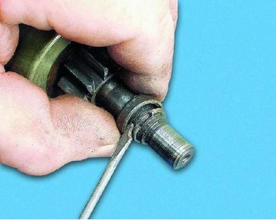
22. Slide the stop ring off the retaining ring.
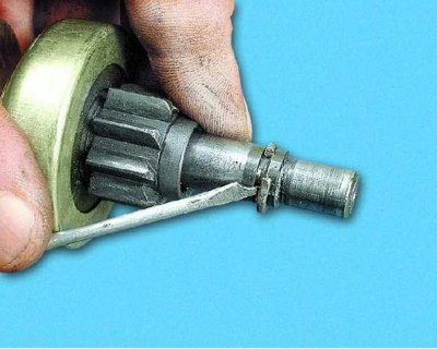
23. Remove the retaining and limiting rings from the armature shaft.
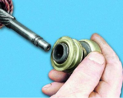
24. Remove the starter drive clutch assembly from the armature shaft.
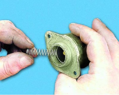
25. Remove the spring from the traction relay.
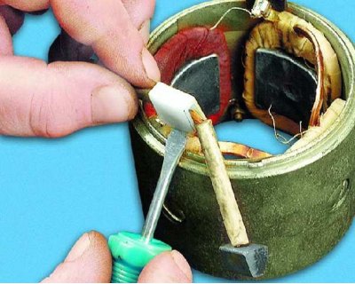
26. To replace the brushes, remove the insulating bracket...
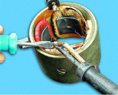
27....heat the junction of the insulated brushes with the stator terminal using a soldering iron and, using a screwdriver to loosen the bend of the stator terminal...
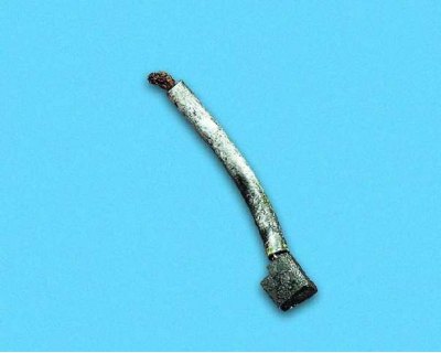
28....remove the insulated brushes.
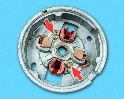
29. Loosen the screws securing the ends of the non-insulated brushes and remove the brushes from the cover on the collector side.
Starter parts defect detection
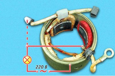
30. Check the condition of the stator winding. To do this, turn on the test lamp (designed for 220 V voltage) into a 220 V AC network and connect one wire to one of the stator winding terminals, and short-circuit the other to the housing. If the lamp lights up, the winding insulation is damaged. Replace the winding or stator. Also check the other stator winding. Be careful when checking with 220 V. Do not touch the stator parts under voltage with your hands.
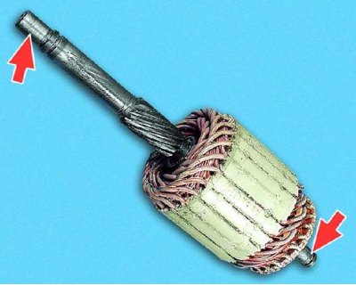
31. Inspect the surfaces of the armature shaft for bearings. If yellow deposits from bearings are found on the armature shaft, remove them with fine sandpaper. There should be no damage on the surface of the shaft splines (burrs, nicks, chipped teeth and visible signs of wear).
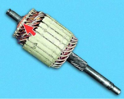
32. Check the reliability of the soldering of the armature winding leads to the collector plates.
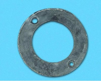
33. The starter housing sealing gasket must not be damaged (breaks, cracks, etc.).
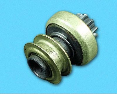
34. Check the starter drive by turning the pinion (it should only rotate in one direction). If the drive parts are badly worn or damaged, replace the drive. If nicks are found on the teeth entry area, grind them with a fine-grained wheel of small diameter.
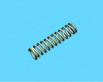
35. Check the condition of the traction relay anchor spring. Replace the broken spring.
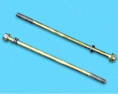
36. The starter tie bolts must not have any significant damage to the threaded portion or heads.
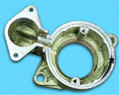
37. Check the condition of the starter cover on the drive side. No cracks are allowed.
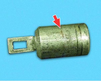
38. Inspect the surface of the traction relay anchor. Deep scratches and burrs are not allowed. The anchor should move in the traction relay easily, without jamming.
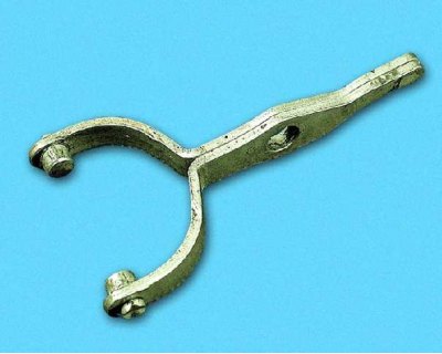
39. The starter drive lever forks must not be bent.
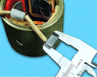
40. Check the condition of the starter brushes by measuring their height. It should be at least 12 mm.
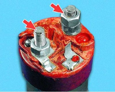
41. Check the closure of the contact bolts of the traction relay with the plate. To do this, connect an ohmmeter to the contact bolts and press the rod of the traction relay (from the flange side). If the ohmmeter shows "infinity", replace the traction relay.
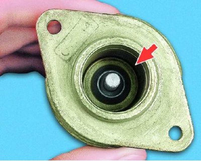
42. Check the condition of the inner surface of the traction relay. No scratches, burrs, etc. are allowed.
Assembling the starter
Assemble the starter in the reverse order of disassembly, taking into account the following features.
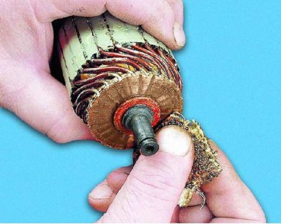
43. Clean the surface of the starter armature commutator.
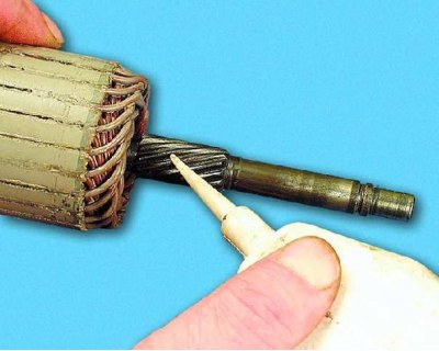
44. Lubricate the splined portion of the armature shaft with engine oil...
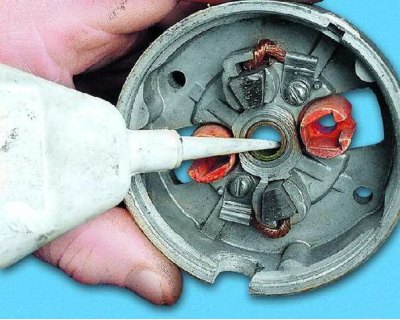
45....the bearing-bushing of the cover from the collector side and...
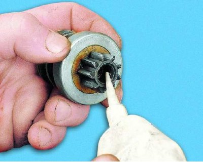
46....sliding surface of the starter drive.
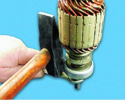
47. Press the stop ring in after installing the retaining ring on the armature shaft.
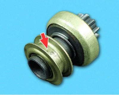
48. Lubricate the starter drive ring with Litol-24 grease.