English Русский
Български
Беларускі
Український
Српски
Hrvatski
Română
Polski
Slovenský
Magyar
| Articles | Contacts | Sitemap |   
Repair and maintenance Lada Repair and maintenance Mazda Repair and maintenance Mitsubishi Repair and maintenance Toyota Repair and maintenance Land Rover Repair and maintenance Hyundai Repair and maintenance Nissan
VAZbook.ru


Main     1111   2101   2105   2106   2107   2109   2110   2115   2121  
VAZ-1111 (1988-1996) VAZ-11113 (1996-2003)
  • Main
  • «Oka»
  • VAZ-11113
  • Electrical equipment
  • Ignition system
  • Repair of the spark timing sensor

Repair of the spark timing sensor (VAZ-11113)

            0

You will need:
  • screwdriver
  • a pointed instrument like an awl
  • beard
  • hammer

Remove the spark timing sensor from the vehicle (see subsection 8.4.3.).
Remove the spark timing sensor from the vehicle (see subsection 8.4.3.).


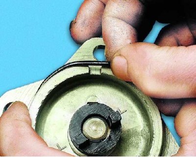
1. Carefully, without using any sharp metal tool, remove the rubber sealing ring from the outer groove of the spark timing sensor housing.
1. Carefully, without using any sharp metal tool, remove the rubber sealing ring from the outer…


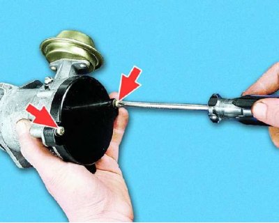
2. Remove the sensor cover by unscrewing the two screws that secure it.
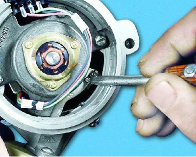
2. Remove the sensor cover by unscrewing the two screws that secure it.


3. Use an awl to remove the vacuum regulator rod spring retainer.
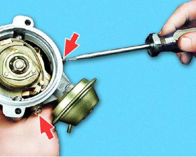


3. Use an awl to remove the vacuum regulator rod spring retainer.


4. Remove the two screws securing the vacuum regulator and...
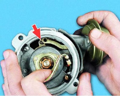
4. Remove the two screws securing the vacuum regulator and...


5....after disconnecting its rod from the sensor support plate pin, remove the regulator.
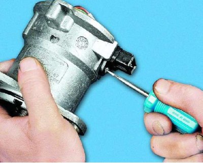
5....after disconnecting its rod from the sensor support plate pin, remove the regulator.


6. Remove the screw securing the Hall sensor wiring harness connector block and...
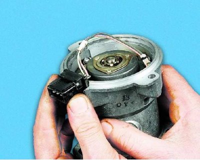
6. Remove the screw securing the Hall sensor wiring harness connector block and...


7....slide the block upwards and remove it from the spark timing sensor housing.
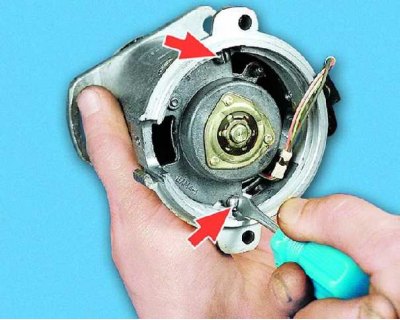

7....slide the block upwards and remove it from the spark timing sensor housing.


8. Remove the two screws securing the front bearing roller holder and...
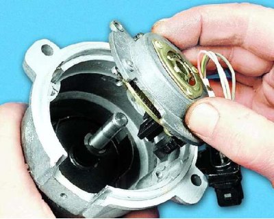
8. Remove the two screws securing the front bearing roller holder and...


9....remove the holder together with the Hall sensor and the support plate.
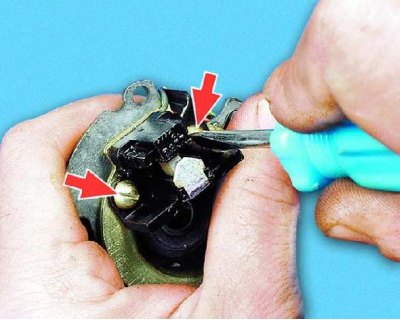
9....remove the holder together with the Hall sensor and the support plate.


10. Remove the two screws securing the Hall sensor to the support plate and...
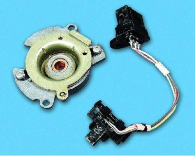
10. Remove the two screws securing the Hall sensor to the support plate and...


11....remove the sensor from it.
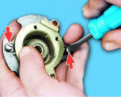
11....remove the sensor from it.


12. Remove the two screws securing the support plate to the front bearing holder and...
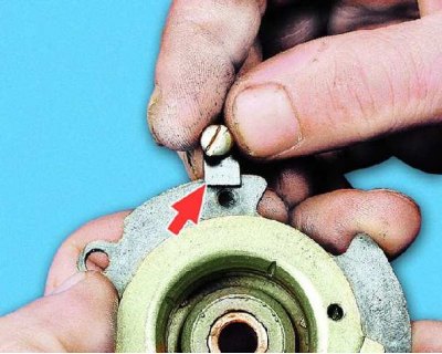
12. Remove the two screws securing the support plate to the front bearing holder and...


13....remove these screws, being careful not to lose the locking plates located underneath them.

13....remove these screws, being careful not to lose the locking plates located underneath them.
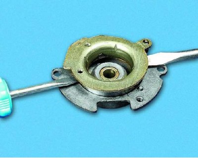

14. Insert two flat-head screwdrivers into the gap between the support plate and the front roller bearing holder and use them to pry the support plate out of the bearing seat...
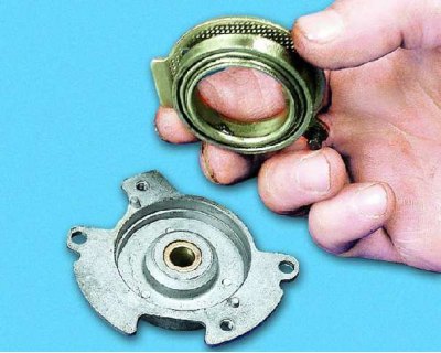
14. Insert two flat-head screwdrivers into the gap between the support plate and the front roller…


15....together with the bearing.

15....together with the bearing.


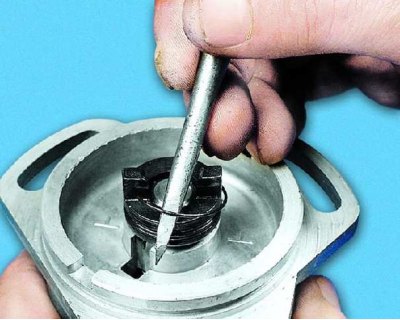
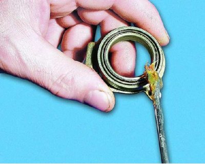
16. Using a pointed tool (an awl), pry up and remove the free end of the coil spring from the groove of the coupling and...
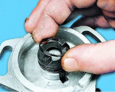
16. Using a pointed tool (an awl), pry up and remove the free end of the coil spring from the…


17....remove the spring.

17....remove the spring.


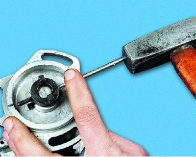
18. Using light hammer blows through a punch of a suitable size, knock the locking pin out of the holes in the coupling and shaft.
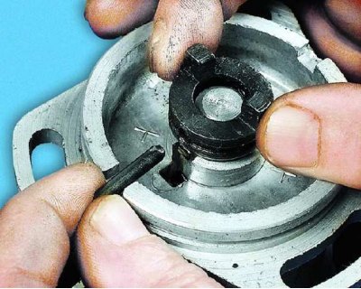
18. Using light hammer blows through a punch of a suitable size, knock the locking pin out of the…


19. Remove the pin through one of the grooves in the end face of the spark timing sensor housing and...
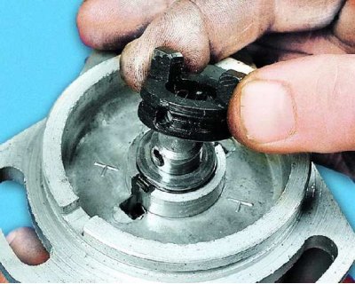
19. Remove the pin through one of the grooves in the end face of the spark timing sensor housing…


20....remove the coupling from the shaft.
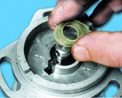
20....remove the coupling from the shaft.


21. Remove the set of spacers from the roller and...
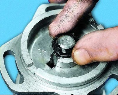
21. Remove the set of spacers from the roller and...


22....a shaped thrust washer.
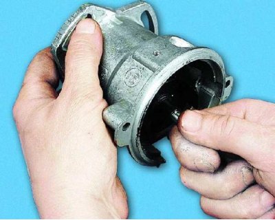
22....a shaped thrust washer.


23. Remove the shaft with the centrifugal regulator and washers from the spark timing sensor housing.
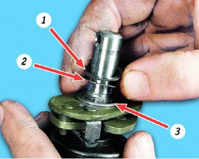
23. Remove the shaft with the centrifugal regulator and washers from the spark timing sensor…


24. Remove the textolite antifriction washers 1, steel adjusting washers 2 (thin) and thrust washers 3 (thick) from the shaft shank.
24. Remove the textolite antifriction washers 1, steel adjusting washers 2 (thin) and thrust…


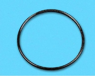
25. Inspect the removed spark timing sensor housing sealing ring. Replace a severely deformed or torn ring.
25. Inspect the removed spark timing sensor housing sealing ring. Replace a severely deformed or…


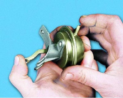
26. Check the removed vacuum regulator by pressing its rod into the housing until it stops...
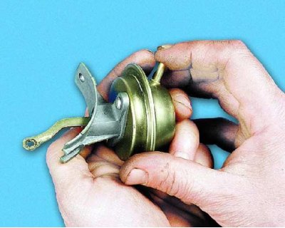
26. Check the removed vacuum regulator by pressing its rod into the housing until it stops...


27....close the vacuum nipple tightly with your finger and release the rod. The rod should remain in the recessed position, and when the nipple is opened, it should move out sharply. If the rod does not stay in the recessed position or does not move out clearly, the regulator is faulty, replace it.
27....close the vacuum nipple tightly with your finger and release the rod. The rod should remain…


28. Carefully inspect the bearing of the support plate and check for grease and ease of rotation. If necessary, wash the bearing with gasoline and put fresh grease in the spaces between the balls.
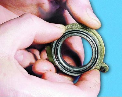
28. Carefully inspect the bearing of the support plate and check for grease and ease of rotation.…


29. If the bearing is seizing or has axial and radial play, replace the support plate and holder assembly with the bearing.
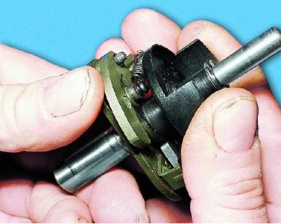
29. If the bearing is seizing or has axial and radial play, replace the support plate and holder…


30. Check the ease of movement of the centrifugal regulator weights and the regulator itself on the shaft. If parts are jammed, wash the unit with gasoline or kerosene and lubricate the moving joints with consistent grease. Check the reliability of the Hall sensor screen fastening on the shaft. Even if there is minor play in the connection, replace the shaft together with the screen.

30. Check the ease of movement of the centrifugal regulator weights and the regulator itself on the…


31. To remove the screen, use a screwdriver to remove the lock washer...
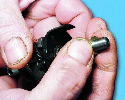
31. To remove the screen, use a screwdriver to remove the lock washer...


32....a spacer washer (if it is installed)...
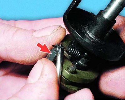
32....a spacer washer (if it is installed)...


33....use a pointed tool to pry the ends of the springs from the regulator base holders (the small spring is hooked onto the holder marked with paint; if the springs are installed incorrectly, the regulator setting will change) and...
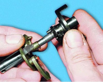
33....use a pointed tool to pry the ends of the springs from the regulator base holders (the small…


34....remove the screen from the roller.
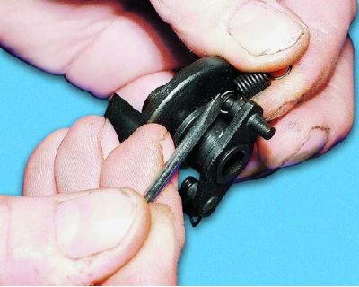
34....remove the screen from the roller.


35. Remove the springs from the screen pins. Note that the large spring is hooked onto the longer pin.
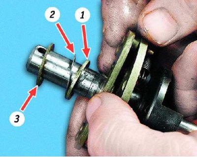
35. Remove the springs from the screen pins. Note that the large spring is hooked onto the longer…


36. Assemble the spark timing sensor in the reverse order of disassembly, lubricating all rubbing surfaces with a thin layer of consistent grease (no more than 0.35 mm) ensure the selection of adjusting washers 2, installed between the thrust 1 and antifriction 3 washers.


This article is available at russian, bulgarian, belarusian, ukrainian, serbian, croatian, romanian, polish, slovak, hungarian
The text was reviewed by the specialist: Grigory Vologodtsev

Share with friends:

Previous articles
VAZ-11113: Ignition system
Next articles

Removal and installation the spark timing sensor
Checking the spark timing sensor
Setting the ignition timing
Checking and replacing the ignition coil
Switch replacement
Checking the ignition switch
Removal and installation the ignition switch
Ignition Switch Repair

More articles from other manuals on VAZ cars:
➠ Repair of the ignition distributor sensor VAZ-21061 (1976-2006)
➠ Crank and valve timing mechanisms VAZ-2101 (1970-1983)
➠ Crank and valve timing mechanisms VAZ-2105 (1979-2010)
➠ Correction of ignition timing angle VAZ-2107 (1982-2012)
➠ Valve timing and cylinder head VAZ-2109 (1984-1997)
Link in different formats to this page


Visitor comments

No comments yet


How much will 22 + 36 ?


VAZ-1111 (1988-1996) 
  • General information
  • Vehicle description
  • Vehicle device
  • Vehicle operation
  • Maintenance
  • Applications
  • Power unit
  • Engine repair
  • Cooling system
  • Lubrication system
  • Supply system
  • Transmission
  • Clutch
  • Transmission
  • Chassis
  • Front suspension and wheels
  • Rear suspension
  • Steering
  • Brake system
  • Body
  • Exterior
  • Interior
  • Electrical equipment
  • Engine electrics
  • Equipment and devices


VAZ-11113 (1996-2003) 
  • General information
  • Introduction to the guide
  • User manual
  • Maintenance
  • Power unit
  • Engine repair
  • Cooling and lubrication system
  • Fuel system
  • Exhaust system
  • Transmission
  • Car gearbox
  • Clutch and drive shafts
  • Chassis
  • Front suspension
  • Rear suspension
  • Steering
  • Brake system
  • Body
  • Exterior
  • Interior
  • Doors and locks
  • Electrical equipment
  • Equipment and devices
  • Lighting and signaling
  • Engine electrics
  • Ignition system


VAZbook.ru © 2017 · Mobile version · Contact with administration · Sitemap: EN BG BY UA RS HR RO PL SK HU · Site search · News and articles VAZ-1111 · VAZ-11113 · VAZ-2101 · VAZ-21011 · VAZ-2104 · VAZ-2105 · VAZ-21051 · VAZ-2106 · VAZ-21061 · VAZ-2107 · VAZ-21099 · VAZ-2109 · VAZ-2108 · VAZ-2110 · VAZ-2112 · VAZ-2114 · VAZ-2115 · VAZ-2121 · VAZ-21213 · VAZ-21214 ·
The site stores technical data using cookies to improve the service.