
English Русский
Български
Беларускі
Український
Српски
Hrvatski
Română
Polski
Slovenský
Magyar
| Articles | Contacts | Sitemap |   
Repair and maintenance Lada Repair and maintenance Mazda Repair and maintenance Mitsubishi Repair and maintenance Toyota Repair and maintenance Land Rover Repair and maintenance Hyundai Repair and maintenance Nissan
VAZbook.ru


Main     1111   2101   2105   2106   2107   2109   2110   2115   2121  
VAZ-1111 (1988-1996) VAZ-11113 (1996-2003)
  • Main
  • «Oka»
  • VAZ-11113
  • Electrical equipment
  • Ignition system
  • Setting the ignition timing

Setting the ignition timing (VAZ-11113)

            0

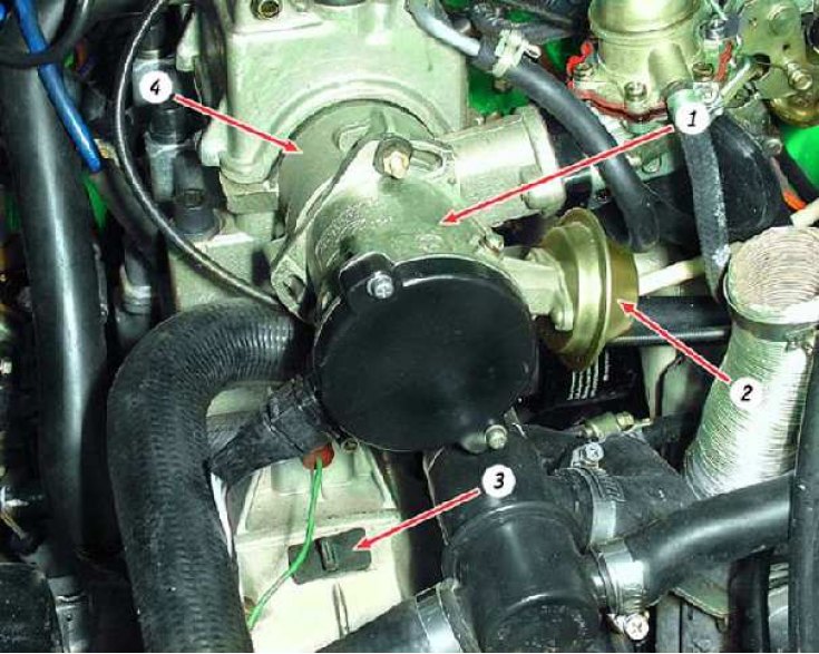
Location of spark timing sensor: 1 – spark timing sensor; 2 – vacuum regulator; 3 – clutch housing…

Location of spark timing sensor: 1 – spark timing sensor; 2 – vacuum regulator; 3 – clutch housing hatch plug; 4 – auxiliary engine drive housing


You will need:
  • key "10"
  • stroboscope (device for checking and setting the ignition timing of carburetor engines)

Before starting work: Remove the air filter.

The ignition timing angle is checked and set at engine idle (at a crankshaft speed of 820–900 min⁻¹). The angle should be within 1°±1° before TDC.

If the ignition timing is set incorrectly, the engine overheats, does not develop full power, and detonation occurs.

Marks for checking the ignition timing
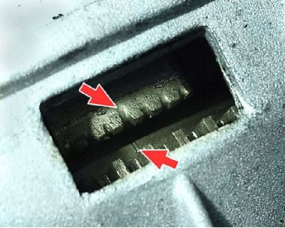


Marks for checking the ignition timing


Check the ignition timing using the mark on the flywheel and the scale of the rear crankshaft oil seal holder (the rubber plug has been removed). When the mark on the flywheel is aligned with the middle division (notch) on the scale, the piston of the first cylinder is set at TDC. One division on the scale corresponds to 2° of crankshaft rotation.


Check the ignition timing using the mark on the flywheel and the scale of the rear crankshaft oil…


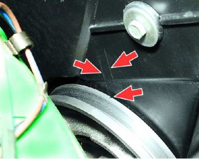
The ignition timing can also be checked and set using the marks on the generator drive pulley and the front cover of the camshaft drive belt. The long mark corresponds to the first cylinder being set to TDC, the short mark corresponds to the ignition timing being advanced by 5° of crankshaft rotation. The ignition timing is set using these marks on the stand.
The ignition timing can also be checked and set using the marks on the generator drive pulley and…


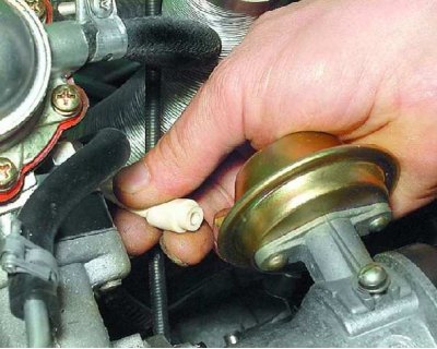
1. Disconnect the hose from the vacuum regulator.
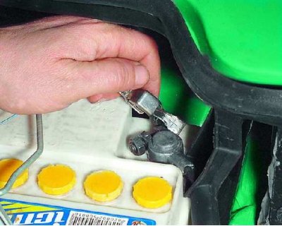
1. Disconnect the hose from the vacuum regulator.


2. To check the ignition timing, connect the "+" clamp of the stroboscope to the "+" terminal of the battery, and...
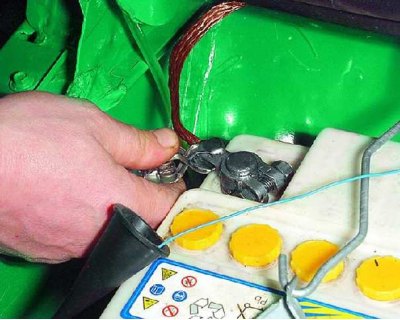

2. To check the ignition timing, connect the «+» clamp of the stroboscope to the «+» terminal of…


3....clamp the "–" terminal of the stroboscope to the "–" terminal of the battery.
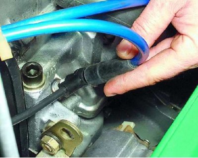
3....clamp the «–» terminal of the stroboscope to the «–» terminal of the battery.


4. Remove the high-tension wire tip from the spark plug of the first cylinder and connect it to the timing light sensor in accordance with the instructions supplied with the timing light.
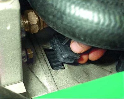
4. Remove the high-tension wire tip from the spark plug of the first cylinder and connect it to the…


5. Remove the rubber plug from the clutch housing hatch.
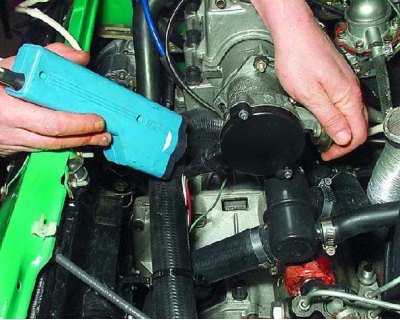
5. Remove the rubber plug from the clutch housing hatch.


6. Start the engine and direct the flashing beam of the strobe light into the clutch housing hatch.
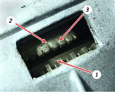
6. Start the engine and direct the flashing beam of the strobe light into the clutch housing hatch.


[The information is posted on the portal: www.vazbook.ru]

7. When the ignition timing is set correctly, mark 1 on the flywheel should be between the middle division 2 and the previous division 3 of the scale. Otherwise, it is necessary to adjust the ignition timing.
7. When the ignition timing is set correctly, mark 1 on the flywheel should be between the middle…


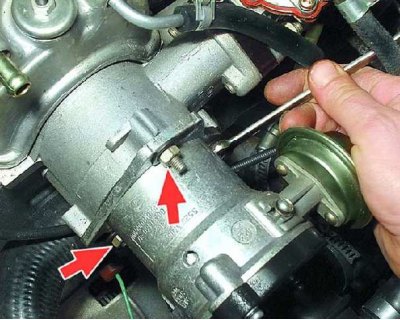
8. To set the ignition timing, loosen the three spark timing sensor mounting nuts.
8. To set the ignition timing, loosen the three spark timing sensor mounting nuts.


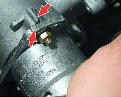
9. To increase the ignition advance angle, turn the sensor housing clockwise (the "-" mark on the sensor housing flange - towards the protrusion on the auxiliary drive housing. In this case, one division on the flange corresponds to 8° of crankshaft rotation).
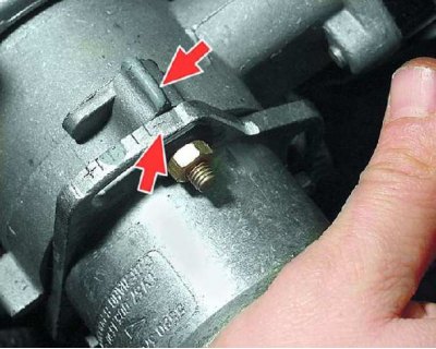
9. To increase the ignition advance angle, turn the sensor housing clockwise (the «-» mark on the…


10. To decrease the ignition advance angle, turn the sensor housing counterclockwise (the "-" mark on the sensor housing flange - to the protrusion on the auxiliary drive housing). Tighten the sensor mounting nuts, check and, if necessary, repeat the ignition timing setting. Connect the hose to the vacuum regulator.


This article is available at russian, bulgarian, belarusian, ukrainian, serbian, croatian, romanian, polish, slovak, hungarian
The text was reviewed by the specialist: Grigory Vologodtsev

Share with friends:

Previous articles
VAZ-11113: Ignition system
Next articles

Checking the spark timing sensor
Removal and installation the spark timing sensor
Repair of the spark timing sensor
Checking and replacing the ignition coil
Switch replacement

More articles from other manuals on VAZ cars:
➠ Setting the ignition timing VAZ-2101 (1970-1983)
➠ Setting the ignition timing VAZ-21051 (1979-2010)
➠ Setting the ignition timing VAZ-2109 (1984-1997)
➠ Setting the ignition timing VAZ-21213 (1994-2006)
➠ Ignition timing — checking and adjustment VAZ-2106 (1976-2006)
Link in different formats to this page


Visitor comments

No comments yet


How much will 29 + 14 ?


VAZ-1111 (1988-1996) 
  • General information
  • Vehicle description
  • Vehicle device
  • Vehicle operation
  • Maintenance
  • Applications
  • Power unit
  • Engine repair
  • Cooling system
  • Lubrication system
  • Supply system
  • Transmission
  • Clutch
  • Transmission
  • Chassis
  • Front suspension and wheels
  • Rear suspension
  • Steering
  • Brake system
  • Body
  • Exterior
  • Interior
  • Electrical equipment
  • Engine electrics
  • Equipment and devices


VAZ-11113 (1996-2003) 
  • General information
  • Introduction to the guide
  • User manual
  • Maintenance
  • Power unit
  • Engine repair
  • Cooling and lubrication system
  • Fuel system
  • Exhaust system
  • Transmission
  • Car gearbox
  • Clutch and drive shafts
  • Chassis
  • Front suspension
  • Rear suspension
  • Steering
  • Brake system
  • Body
  • Exterior
  • Interior
  • Doors and locks
  • Electrical equipment
  • Equipment and devices
  • Lighting and signaling
  • Engine electrics
  • Ignition system


VAZbook.ru © 2017 · Mobile version · Contact with administration · Sitemap: EN BG BY UA RS HR RO PL SK HU · Site search · News and articles VAZ-1111 · VAZ-11113 · VAZ-2101 · VAZ-21011 · VAZ-2104 · VAZ-2105 · VAZ-21051 · VAZ-2106 · VAZ-21061 · VAZ-2107 · VAZ-21099 · VAZ-2109 · VAZ-2108 · VAZ-2110 · VAZ-2112 · VAZ-2114 · VAZ-2115 · VAZ-2121 · VAZ-21213 · VAZ-21214 ·
The site stores technical data using cookies to improve the service.