

The ignition timing must also be adjusted depending on the amount of mixture entering the cylinders: the more it is, the less the advance should be, and vice versa. The control and adjustment of these changes occur automatically, but in order for the entire system to work in the required modes, the moment of ignition of the mixture must be precisely adjusted. How important this is can be judged by the results that occur with improper adjustment: with late ignition due to incomplete combustion of the working mixture, the engine loses power, throttle response, overheats and spends more fuel; with too early ignition, detonation knocks occur, burnouts of pistons and valves occur. The engine also loses power.
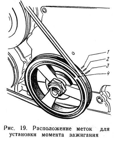
The moment of ignition is set by coincidence of label 4 (pic. 19), located on the crankshaft pulley, and marks 1, 2, 3 on the timing cover. Equipping the operation with a tool depends on the chosen method of setting the ignition moment. The traditional and most affordable way is with a 12-volt test lamp. It is used if there is no special equipment. The second method is using a stroboscope, which allows you to achieve the greatest accuracy in adjustment.
With the first method you must have the following tools and fixtures: a starting handle, a test lamp with two soldered wires and a 13 mm wrench. The sequence of the operation is as follows:
- remove the cover of the breaker-distributor;
- turn the crankshaft with the starting handle to a position where the difference plate 1 (see fig. 16) rotor 2 will be directed towards the contact of the wire of the first cylinder in the cover, and mark 4 (see fig. 19) on the crankshaft pulley coincides with mark 2 on the timing cover. This will correspond to the position of the piston of the first cylinder at the end of the compression stroke;
- loosen nut 11 (see fig. 16) fastening the body 12 of the distributor;
- connect a test lamp with one end of the wire to terminal 6, and with the other - to ground and turn on the ignition;
- turn the housing 12 of the distributor clockwise until the breaker contacts close (while the lamp should go out);
- slowly turn the distributor housing counterclockwise until the control lamp lights up. In this case, the rotor 2 should be slightly pressed to select the gap;
- set the distributor housing to the position when the control lamp lights up (the breaker contacts will be in the initial opening phase), and, holding the housing in this position, tighten the distributor mounting nut.
To clarify the ignition timing, it is corrected with an octane corrector nut or by turning the breaker-distributor itself on a warm engine. Moving on a flat road in direct gear at a speed of 50 km / h, sharply press the fuel control pedal. If this causes a slight and short-term detonation, then the lead angle is set correctly. With strong detonation (early ignition) the housing of the breaker-distributor should be turned clockwise, in the absence of detonation (late ignition) - counterclock-wise. After correcting the ignition timing, its correctness is checked again on a moving vehicle.
With the second method use a stroboscope and a 13 mm key. The domestic industry has mastered the production of strobe lights operating from the vehicle's on-board network. The stroboscope STB-1 proved to be the best. The device is included in the engine ignition system so that the flashes of the strobe lamp occur synchronously with the appearance of a spark between the electrodes of the spark plug of the first cylinder. Before starting to check the ignition timing, the breaker-distributor is set to zero, and mark 4 (see fig. 19) on the crankshaft pulley for better visibility mark with chalk. When the engine is running, the light of a strobe flash lamp is directed onto a rotating pulley. Due to the fact that the flashes of the lamp and the sparks at the candle occur at the same time, the mark on the pulley seems to be stationary. If the ignition timing is set correctly, then when the engine is running at low (800-900 rpm) crankshaft speed, mark 4 will always be located opposite mark 3 on the timing cover. If the ignition timing is incorrectly set, the error is eliminated by turning the body of the breaker-distributor to the required angle.
To increase the ignition timing, the housing of the breaker-distributor should be turned counterclockwise, and to decrease it, clockwise. The perfection of the stroboscopic method lies primarily in the fact that the process of control and adjustment is carried out on a running engine. This makes it possible to simultaneously check the performance of the centrifugal and vacuum ignition timing controllers. Considering the complex organization of systems and mechanisms of a modern engine, preference should be given to the stroboscopic method.
Since a stroboscope is not always and not always possible to buy, motorists adapt other devices for these purposes.
As an example, we can describe the proposal of a craftsman from Dushanbe, who adapted a FIL-102 flash unit as a stroboscope. To implement this task, a storage capacitor C4 was built into the flash circuit (pic. 20) and mode switch «stroboscope» contact S1.
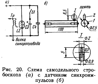
How does this device work? In mode «stroboscope», when contact S1 is open, only capacitor C4 is included in the power circuit, the capacitance of which is 3 uF. In mode «flash» (with closed contact S1) the main storage capacitor C3 with a capacity of 1500 microfarads also works.
The innovator made a simple design of a capacitive-type sensor 100 mm long and installed it on a high-voltage wire. A socket 2 is made on the sensor for one central electrode, with the help of which the plug of the flash sync line is connected to the sensor. In mode «flash» the device connected to the sensor works as a stroboscope. Switch 1 is made of two instrument clamps separated by a jumper plate.