




Contents: Disassembly ↓ Assembly ↓
Disassembly
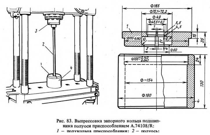
The half rings of the A.74108/R device (Fig. 83) encircle the bearing and install the axle shaft vertically so that the half rings rest on the thrust ring. Place the axle shaft under a press and apply a gradually increasing force to the splined end of the axle shaft until the locking ring is removed. This ring is not reused but replaced with a new one. Check whether the seating surface of the axle shaft has any scratches or damage. If necessary, replace the axle shaft with a new one.
Assembly
Install the axle shaft 2 vertically (Fig. 84), resting its flange on ring 1 (A. 74107/R) devices. Install the axle bearing oil deflector and the mounting plate 6 with the gasket, previously connected to each other with two screws, onto the axle shaft, install the axle bearing 3. Insert the new locking ring 5 into the special cage 7 (A.74107/4R), place the ring in an oven and heat it up to approximately 300 C so that at the moment of pressing it onto the axle shaft its temperature is 220–240°C.
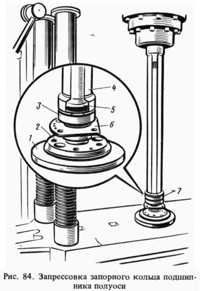
The locking ring is pressed onto the axle shaft using a mandrel 4 (A.74107/2R) on a press with a force of no more than 6000 kgf so that the inner ring of the bearing is clamped between the locking ring and the flange of the axle shaft.
The article is copied from the website (VazBook.ru)
After pressing, make sure that the ring does not shift under an axial load of 2000 kgf. To do this, install the axle shaft assembly on the A.95601/R device (Fig. 85) and clamp the locking ring 4 in a special vice. Attach the indicator 1 with a division value of 0.01 mm to the flange of the axle shaft 2. After setting the indicator pointer to zero, apply the specified axial load, creating a tightening torque of 8-8.5 kgf·m with the torque wrench 3 on the screw rests against the end of the axle shaft, through the ball rests against the end of the axle shaft. In this case, not even the smallest gap should appear between the locking ring and the inner ring of the bearing 5.
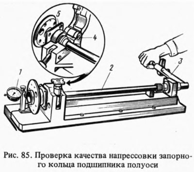
After removing the load and unscrewing the screw of the device, the indicator pointer should return to the zero position. This proves that no shift of the locking ring on the axle shaft has occurred. Otherwise, it is necessary to replace the axle shaft with a new one.