
Determine the resistance of the recoil and compression stroke by the largest ordinates of the corresponding diagrams. Chart Curve (pic. 174) should be smooth, and at the transition points (from recoil to compression stroke) without sections parallel to the zero line.
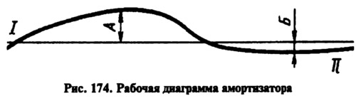
The highest point of the recoil stroke curve at a scale of 4.8 kgf per 1 mm should be located at a distance A from the zero line, equal to 21-28 mm for the front shock absorbers and 19-26 mm for the rear. The highest point of the compression stroke curve at the same scale should be at a distance B from the zero line, equal to 3.5-6.5 mm for the front shock absorbers and 4.5-7.5 mm for the rear. After checking the shock absorber, remove it from the stand and, if necessary, sort it out and replace damaged or worn parts. To make sure that the shock absorber is working, repeat the test.