
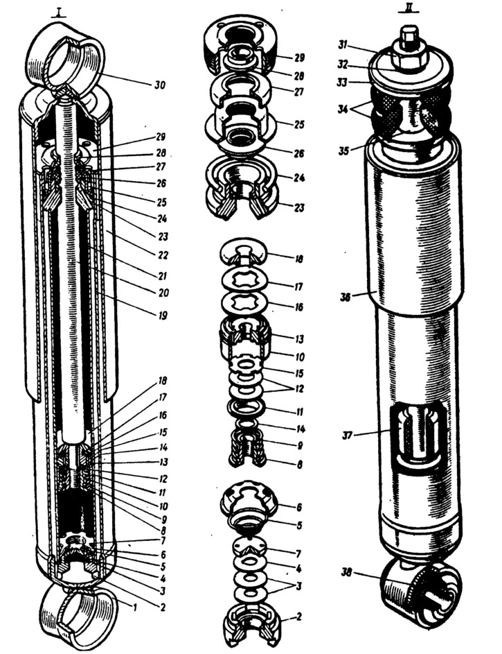
Pic. 172. Front and rear shock absorbers:
1 - lower eye; 2 - valve body compressed; 3 - compression valve disks; 4 - valve throttle disc compressed; 5 - valve spring compressed; 6 - clip of the compression valve; 7 - compressed valve disc; 8 - recoil valve nut; 9 - recoil valve spring; 10 - piston; 11 - recoil valve plate; 12 - recoil valve disks; 13 - piston ring; 14 - washer of the recoil valve nut; 15 - throttle disc of the recoil valve; 16 - bypass valve plate; 17 - bypass valve spring; 18 - restrictive plate; 19 - tank; 20 - stock; 21 - cylinder; 22 - casing; 23 - rod guide sleeve; 24 - tank sealing ring; 25 - holder of the stuffing box; 26 - stem gland; 27 - gasket of the protective ring of the rod; 28 - protective ring of the rod; 29 - tank nut; 30 - the upper eye of the shock absorber; 31 - nut for fastening the upper end of the front suspension shock absorber; 32 - spring washer; 33 - washer of the shock absorber mounting cushion; 34 - pillows; 35 - spacer sleeve; 36 - front suspension shock absorber casing; 37 - stock buffer; 38 - rubber-metal hinge.
During the compression stroke, the liquid under pressure of the piston 10, overcoming the resistance of the flat spring 1 (pic. 173) bypass valve 2 flows from the under-piston space to the over-piston space. All the liquid displaced cannot pass in this way, since the inserted rod 8 occupies a part of the volume released by the piston, therefore the other part of the liquid, bending the inner edges of the disks 6, flows from the cylinder into the reservoir. With a smooth stroke of the rod 8, the force from the liquid pressure will not be sufficient to press the inner edges of the disks 6 from the plate 5, and the liquid will pass into the tank through the cutout of the loosel sheet 4 (see fig. 172).
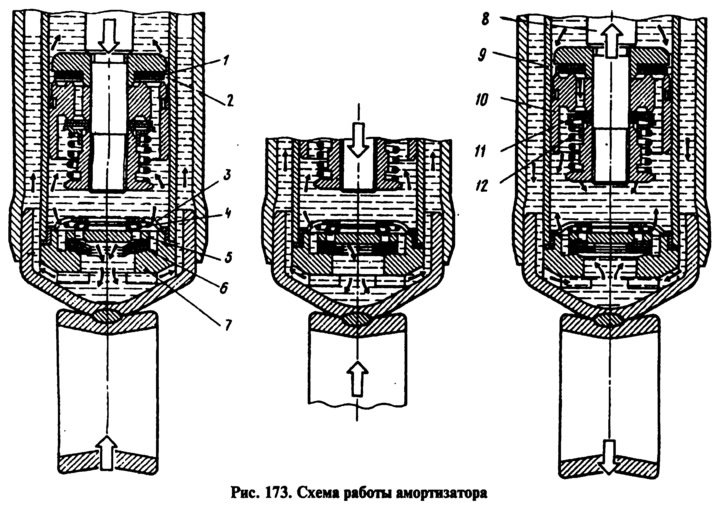
When the return stroke over the piston 10 (see fig. 173) pressure is created, and a vacuum is created under the piston. The liquid from above the piston space, overcoming the resistance of the spring 12, bends the outer edges of the disks 11 of the recoil valve and flows into the lower part of the cylinder 9. In addition, due to rarefaction, part of the liquid from the reservoir, bending the outer edges of the disks 6 of the compression valve, fills the lower part of the cylinder. At a low piston speed, when the fluid pressure is insufficient to press the recoil valve disks, the liquid through the side cutouts of the throttle disk 15 (see fig. 172) will be throttled, creating resistance to the recoil.