
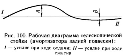
Chart Curve (pic. 100) should be smooth, and at the point of intersection (from compression stroke to recoil stroke) - without sections parallel to the zero line.
The resistance of the compression and recoil stroke is determined by the greatest effort received when removing the diagram. The control values of the forces on the diagrams of the telescopic strut and the shock absorber are determined at a temperature (20±5) °C.
The highest point of the compression stroke curve at a scale of 47 N per 1 mm should be from the zero line at a distance B equal to (3±0,75) mm [ (141,3±35,3) H] for the telescopic pole and (6±1,1) mm [ (282,5±58,9) H] for the rear shock absorber.
The highest point of the recoil stroke curve at the same scale should be from the zero line at a distance A equal to (9,5±1,1) mm [ (447,3±58,9) H] for the telescopic pole and (17±2) mm [ (800,5±94,2) H] for the rear shock absorber.
After checking, remove the telescopic rack (shock absorber) from the stand and, if necessary, disassemble it, replacing damaged or worn parts. After assembly, repeat the test to make sure the rack is in good condition (shock absorber).