
rear axle beam (suspension guide) connected to the body with four longitudinal and one transverse rods. Like longitudinal bars 3 and 17 (pic. 170), and transverse 22 at one end are pivotally connected to the brackets 8, 18 and 19 of the body by means of bolts 7, and at the other end to the beam brackets. Swivel joints are identical in design and differ only in size. Each hinge consists of a rubber bushing 2 through which a metal bushing 1 passes.
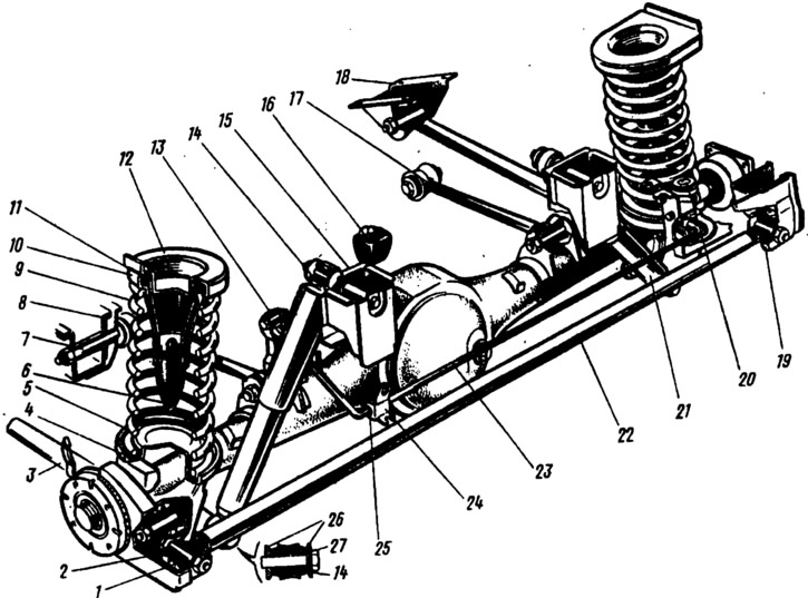
Pic. 170. Rear suspension:
1 - spacer sleeve; 2 - rubber bushing; 3 - lower longitudinal rod; 4 - lower insulating gasket of the spring; 5 - lower support cup of the spring; 6 - suspension compression stroke buffer; 7 - bolt for fastening the upper longitudinal rod; 8 - bracket for fastening the upper longitudinal rod; 9 - suspension spring; 10 - upper spring cup; 11 - the upper insulating gasket of the spring; 12 - spring support cup; 13 - thrust lever drive pressure regulator; 14 - rubber bushing of the shock absorber eye; 15 - shock absorber mounting bracket; 16 - additional suspension stroke buffer; 17 - upper longitudinal rod; 18 - bracket for fastening the lower longitudinal rod; 19 - the bracket is attached to the transverse rod to the body; 20 - pressure regulator; 21 - shock absorber; 22 - transverse rod; 23 - the regulator drive lever is pressed; 24 - holder of the support bushing of the lever; 25 - lever bushing; 26 - washer; 27 - remote bushing.
Springs are the elastic element of the suspension. The lower end of the spring rests on the lower support cup 5 through a plastic insulating gasket 4, the upper end rests on the upper support cup 12 welded to the body. A rubber gasket 11 is installed between the support cup and the spring cup 10. The springs of the rear suspension of cars, as well as the front suspension, are divided into two groups: A and B. The springs of group A are marked with light brown (VAZ-2104) or yellow (VAZ-2105) paint on the outside of the turns, and group B - blue (VAZ-2104) or green (VAZ-2105) paint.
Hydraulic dampers 21 (damping suspension elements) fastened with one lug to the bracket 15 of the body, the other - to the bracket of the rear axle beam by means of rubber bushings 14, washers 26 and bushings 27. The course of the rear axle beam is limited by two main 6 and additional 16 compression buffers.
In the zone of the rear axle beam, a rear brake pressure regulator 20 is attached to the body, which is connected to the rod 13 mounted on the beam by means of a lever 23 fixed to the body with the help of a sleeve 25 and a clip 24.