
Chart Curve (pic. 87) should be smooth, and at the transition points (from compression stroke to recoil stroke) without sections parallel to the zero line.
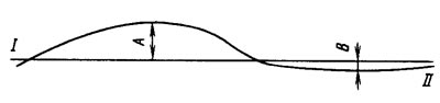
Pic. 87. Working diagram of the telescopic suspension strut (shock absorber): 1 - effort during recoil; 11 - force during the compression stroke
The resistance of the compression and recoil stroke is determined by the largest ordinates of the diagram. The control values of the ordinates on the diagrams of the telescopic strut and shock absorber are set for struts and shock absorbers at a temperature (20±5) °C The highest point of the compression stroke curve at a scale of 4.8 kgf per 1 mm should be from the zero line at a distance B equal to 3.25 mm±0.5 mm (15.6±2.4 kgf) for telescopic stand and 5.25 mm±0.75 mm (25.2±3.6 kgf) for rear shock absorber.
The highest point of the recoil stroke curve at the same scale should be from the zero line at a distance A equal to 13 mm±1.5 mm (62.4±7.2 kgf) for telescopic pole and 12 mm±1.25 mm (57.6±6 kgf) for rear shock absorber.
After checking, remove the telescopic rack (shock absorber) from the stand and, if necessary, disassemble it, replacing damaged or worn parts. After assembly, repeat the test to ensure that the telescopic strut is in good working order (shock absorber).