




Lubrication system (figure 12) consists of an oil pump, oil filter, crankcase, oil filler neck on the cylinder head cover, oil level indicator in the crankcase, as well as channels in the block and cylinder head. The minimum oil pressure in the system is monitored by sensor 10, which is screwed into the hole in the flange of the oil filter, connected by a channel to the main oil line in the cylinder block. The minimum oil pressure should be at least 0.08 MPa at a crankshaft speed of 820-900 min⁻¹. When the pressure drops below the permissible value, the control lamp of the light panel lights up red.
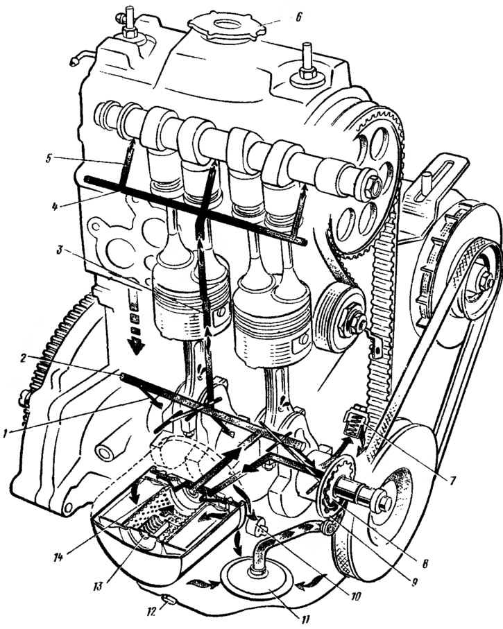
Figure 12. Lubrication system: 1 — oil supply channel to the main bearing; 2 - main oil line; 3 - vertical channel in the cylinder block; 4 - oil line in the cylinder head; 5 — oil supply channel to the camshaft bearing journal; 6 — oil filler cap; 7 — pressure reducing valve; 8 - oil pump drive gear; 9 — driven gear of the oil pump; 10 — oil pressure warning light sensor; 11 — oil receiver; 12 - drain plug; 13 — oil filter bypass valve; 14 — oil filter anti-drain valve.
Oil pump
Gear, with internal gears, is located on the front end of the crankshaft. The pump consists of a cover, a housing with suction and discharge cavities and an oil receiver. The leading 1 (figure 13) and driven 5 gears. To ensure the necessary clearances between the gears and the housing when the temperature changes, the housing is cast from cast iron, the gears are made of metal ceramics. In the housing, the suction cavity is separated from the discharge cavity by a sickle-shaped projection 4.
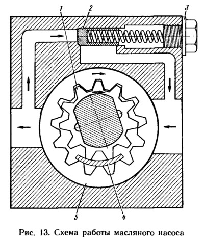
Presenter (with external teeth) and the driven gear of the pump suck in oil and feed it into the pump discharge cavity with the tooth cavities. At a pressure above 0.45 MPa, the pressure reducing valve 2 opens and part of the oil is bypassed into the pump suction cavity.
An aluminum ring 3 is placed under the plug of the pressure-reducing valve. The crankshaft in the pump cover is sealed with a rubber seal. The pump oil receiver is sealed with a rubber ring.
The oil pump is interchangeable with the VAZ-2108 engine pump.
Oil filter
Interchangeable with the oil filter of the VAZ-2105 engine. The filter is full-flow, non-separable. A filter element made of special cardboard is installed in the steel housing.
Crankcase ventilation
Forced, closed, preventing the release of crankcase gases into the atmosphere. When the engine is running, crankcase gases are released through the lower exhaust hose 9 (figure 14) are sucked into the oil separator (cavity), which is closed by cover 6. Then the crankcase gases are sucked through the upper exhaust hose 5 and the crankcase gas outlet hose 2 and enter the engine combustion chambers with the combustible mixture.
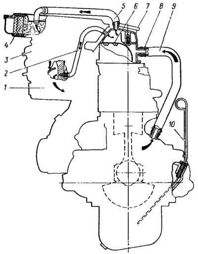
Figure 14. Engine crankcase ventilation diagram: 1 - inlet pipe; 2 — hose for removing crankcase gases into the carburetor's throttle space; 3 - carburetor; 4 — air filter element; 5 - Upper exhaust hose; 6 - oil separator cover; 7 — oil filler cap; 8 — exhaust hose branch; 9 - lower exhaust hose; 10 — oil level indicator.