
Lubrication of rubbing parts, along with the selection of materials and the type of treatment of their surfaces, increases the durability of the engine. Purification of the circulating oil from mechanical and other impurities is provided by an oil filter with a paper filter element.
Engine oil has a complex of additives that provide high lubricating properties of the oil, resistance to oxidation and the ability to work in a wide temperature range.
The oil reserve necessary for normal operation of the engine is located directly in the oil sump 20 (pic. 36) engine. Oil is filled into the engine crankcase through the oil filler neck, hermetically sealed with cover 2. The oil level is controlled by the marks on the indicator. Waste oil is drained from the system through a hole closed by a threaded drain plug 19. The capacity of the lubrication system is 3.5 liters.
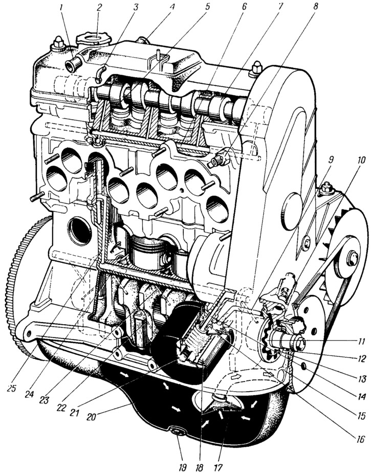
Pic. 36. Lubrication system:
1 - branch pipe for exhausting charter gases into the air filter housing; 2 - oil filler cap: 3 - crankcase exhaust pipe into the throttle space of the carburetor; 4 - branch pipe of the exhaust hose; 5 oil supply channel to the camshaft bearing; 6 - oil line in the block head; 7 - camshaft; 8 - oil pressure warning lamp sensor; 9 - oil supply channel from the pump to the filter; 10 - pressure reducing valve of the pump; 11 - oil pump drive gear; 12 - driven gear of the oil pump; 13 - sickle-shaped protrusion between the gears; 14 - oil supply channel from the filter to the main oil line: 15 - oil supply channel from the oil receiver to the pump; 16 - anti-drainage valve; 17 - oil receiver; 18 - filter element; 19 - drain plug; 20 - oil sump; 21 - bypass valve; 22 - oil supply channel from the main bearing to the connecting rod; 23 - oil supply channel to the main bearing of the crankshaft; 24 - main oil line; 25 - channel for supplying oil from the main line to the block head line.
The engine lubrication system is combined, in which part of the parts is lubricated under pressure, part by gravity and part by spraying. Under pressure, the main and connecting rod bearings of the crankshaft, camshaft bearings are lubricated. Oil flowing from the gaps and sprayed by moving parts lubricates the cylinder walls, pistons with piston rings, piston pins in piston bosses, camshaft cams, valve lifters, and valve stems in their guide bushings.
The lubrication system includes an oil sump 20, an oil receiver 17 with a filter mesh, an oil pump and a pressure reducing valve 10, a system of oil channels in the block and cylinder head, a crankshaft, a full-flow oil filter with a filter element 18, a bypass valve 21 and an anti-drain valve 16, a pointer oil level and oil filler neck.
All components of the system on the considered vehicles are interchangeable. The minimum oil pressure in the system is controlled by a sensor 8, which is screwed into the hole of the oil line 6 in the cylinder head, connected to the main oil line 24 in the cylinder block. Oil pressure must be at least 0.8 kgf/cm2 at 750... 800 rpm. When the oil pressure drops below the permissible level, one of the control lamps of the light panel lights up in red «Stop» on the instrument panel.
The circulation of oil during engine operation is as follows. The oil pump, located at the front end of the crankshaft, sucks oil through the filter mesh of the oil receiver 17, the suction pipe and the channel in the pump housing and delivers it through the channel 9 in the cylinder block to the full-flow oil filter. In the filter, the oil is purified from mechanical impurities and resinous substances. The filtered oil through channel 14 enters the main oil line 24, which runs along the cylinder block, and from there it is supplied through channels 23 in the partitions of the cylinder block to the crankshaft main bearings. The main bearing shells have two holes through which oil penetrates into the annular grooves on the inner surface of the shells. From these grooves, part of the oil goes to lubricate the main bearings, and the other part through the channels drilled in the necks and cheeks of the crankshaft to the bearings of the lower heads of the connecting rods. From the side hole of the connecting rod bearing, a jet of oil enters the cylinder mirror at the moment the bearing hole coincides with the channel in the connecting rod journal. The oil removed from the cylinder walls by the oil scraper ring is discharged through the holes in the piston into the piston and lubricates the piston pin bearings in the piston bosses.
In the connecting rod journals of the crankshaft, centrifugal cleaning of the oil also takes place from foreign impurities contained in the oil, which accumulate in inclined channels under the action of centrifugal forces in the space from the holes in the connecting rod journal to the plug of the crankshaft oil channel.
From the main oil line, oil is also supplied through a vertical channel 25 in the block and cylinder head to the oil line 6 of the cylinder head, and from there through channels 5 to the camshaft bearings. The oil flowing from the camshaft bearings lubricates the working surfaces of the cams and valve lifters. The oil collected under the cylinder head cover drains to the left side of the engine and drains through the ports in the head and channels in the cylinder block into the oil sump.
The oil pressure on a warm engine at an average speed of the crankshaft is 3.5... 4.5 kgf / cm2.
In order to ensure the necessary oil pressure in the line when the engine is running in any mode, as well as to compensate for the oil consumption that increases as the engine wears out, the oil pump has an excess capacity.