

Setting the fuel level in the float chamber
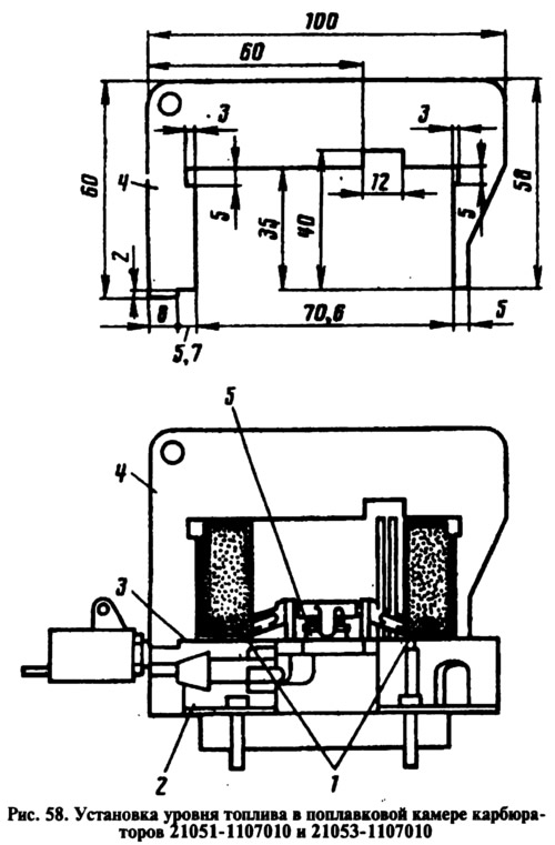
Correct installation of float 1 (pic. 58) check with gauge 4, for which set it perpendicular to cover 2 with gasket 3. The cover must be held horizontally with the floats up. There must be a gap of no more than 1 mm between the gauge along the contour and the floats. Adjust if necessary by bending the tongue and float arms. The bearing surface of the tongue must be perpendicular to the axis of the needle valve 5 and must not have dents or nicks.
Trigger Adjustment
When turning lever 4 (pic. 59) control of the air damper 5 fully counterclockwise, the air damper must be fully closed under the action of the spring 7. If the damper does not close, eliminate the cause of jamming.
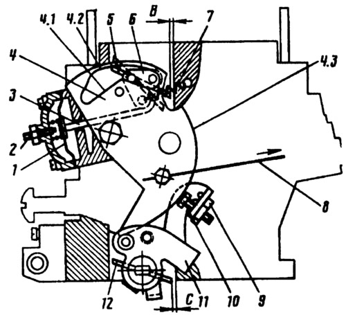
Pic. 59. Carburettor starter 21051-1107010, 21053-1107010:
1 - diaphragm; 2 - adjusting screw; 3 - diaphragm rod; 4 - air damper control lever; 4.1 - lower profile of the groove of the lever 4 to limit the maximum opening of the air damper; 4.2 - the upper profile of the groove of the lever 4, which provides mechanical opening of the air damper; 4.3 - the edge of the lever 4 to ensure the starting clearance of the throttle valve of the first chamber; 5 - air damper; 6 - air damper lever; 7 - air damper return spring; 8 - air damper drive rod; 9 - adjusting screw stopper; 10 - adjusting screw for slightly opening the throttle valve of the first chamber; 11 - throttle control lever; 12 - throttle valve of the first chamber.
With the air damper fully closed, press manually on the rod 3 of the starting device until it stops. In this case, the air damper should open by 3.0 mm (starting clearance B). If necessary, adjust it with screw 2.
The throttle valve of the first chamber with a fully closed air damper should be ajar by 1.2 mm (starting gap C). For carburetor 21053-1107010 - 1.1 mm. Adjust this gap with screw 10.
Checking the operation of the second camera blocking mechanism
Turn the choke control lever counterclockwise until the choke is fully closed. Then turn the throttle actuator lever until the throttle valve of the first chamber is fully open, while the throttle valve of the second chamber should remain in the closed position.
Turn the choke control lever clockwise and the throttle control lever until the dampers are fully open. If the second chamber throttle does not open, repair the problem. The reason may be that the lock lever of the second chamber is stuck or the spring of the lock lever is disconnected.