
Disassembly
Unscrew the screws securing the carburetor cover and carefully disconnect it from the body so as not to damage the gasket, float and tube of the second chamber adapter system.
Disassemble the lid (pic. 52) carburetor in the following order:
- using a mandrel 3x24.5 mm, carefully push the axis 13 of the float 15 out of the posts and, without damaging the tongues of the float, disconnect it from the cover;
- remove gasket 16, unscrew seat 4 of the needle valve;
- unscrew the branch pipe 7 of the fuel supply and remove the fuel filter 5;
- unscrew the housing 2 with the idle fuel jet and with the electromagnetic shut-off valve 1, remove the jet;
- unscrew axle 11, remove ball 9 with spring, remove choke control lever 10, disconnect choke lever spring;
- if necessary, unscrew the screws securing the air damper 6, remove the damper and the axle 8 with the lever.
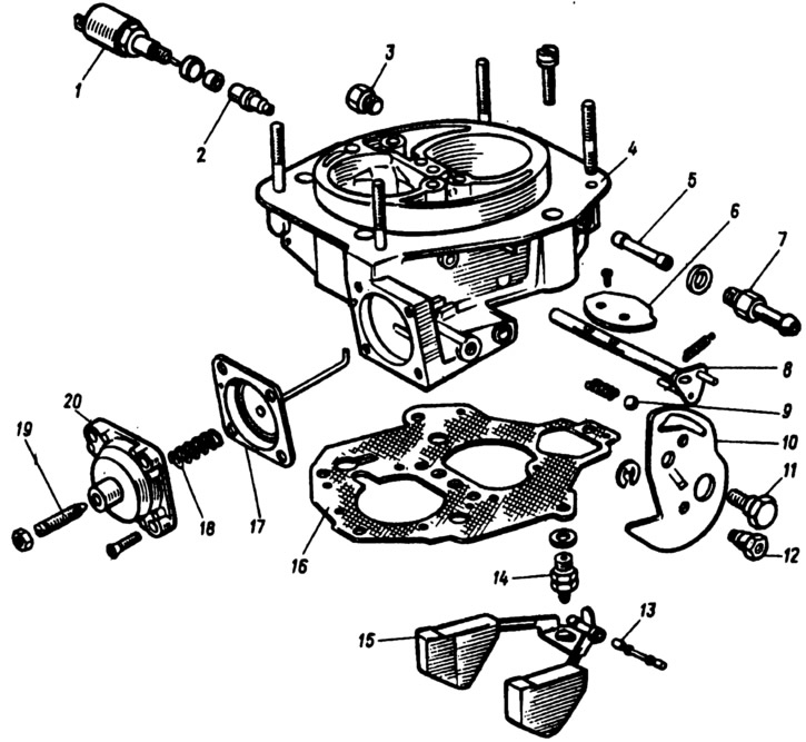
Pic. 52. Details of the cover of carburetors 21051-1107010 and 21053-1107010:
1 - electromagnetic shut-off valve; 2 - housing with an idle fuel jet; 3 - cork; 4 - carburetor cover; 5 - fuel filter; 6 - air damper; 7 - fuel supply pipe; 8 - axis of the air damper with a lever; 9 - ball for fixing the air damper control lever; 10 - air damper control lever; 11 - axis of the lever 10, 12 - bushing for fastening the air damper drive rod; 13 - float axis; 14 - seat with needle valve; 15 - float; 16 - gasket; 17 - diaphragm of the starting device with a rod; 18 - spring; 19 - adjusting screw; 20 - starter cover.
Disassemble the diaphragm trigger by unscrewing the screws and removing the cover 20 complete with the adjusting screw 19. Remove the spring 18 and the diaphragm 77 with the stem.
Disassemble the carburetor body (pic. 53).
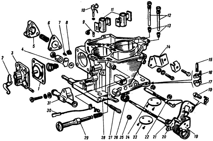
Pic. 53. Carburetor body parts 21051-1107010 and 2107-1107010:
1 - accelerator pump diaphragm; 2 - accelerator pump drive lever; 3 - cover; 4 - accelerator pump drive cam; 5 - power modes economizer cover; 6 - economizer diaphragm; 7 - economizer fuel jet; 8 - economizer valve; 9 - check valve of the accelerator pump; 10 - sprayers of the accelerator pump with a fuel supply valve; 11 - sprayers of the main dosing systems; 12 - main air jets with emulsion tubes; 13 - main fuel jets; 14 - bracket for fastening the shell of the draft of the air damper drive; 15 - adjusting screw of the second chamber; 16 - adjusting screw stopper; 17 - stopper cap; 18 - adjusting screw for slightly opening the throttle valve of the first chamber; 19 - axis of the throttle valve of the first chamber with drive levers; 20 - lock lever of the second chamber; 21 - lock lever spring; 22 - axis of the throttle valve of the second chamber; 23 - throttle valve of the first chamber; 24 - throttle valve of the second chamber; 25 - plug; 26 - return spring of the throttle actuator lever of the second chamber; 27 - quality adjustment screw (composition) idle mixtures; 28 - carburetor body; 29 - adjusting screw for the amount of idle mixture; 30 - electrical wire with a limit switch for the forced idle economizer; 31 - carburetor heating block.
For this:
- unscrew the mounting screws, remove the cover 3 of the accelerator pump with lever 2 and diaphragm 1;
- remove nozzles 10 and 11 of the accelerator pump and nozzles of the main dosing systems of the first and second chambers. Take out the atomizers 10 of the accelerating pump only by the body of the atomizers;
- unscrew the nut of the throttle valve axis of the first chamber, remove the cam 4 of the accelerator pump drive and the washer. Unscrew the fastening screw and remove the electrical wire 30 with the economizer limit switch for forced idling;
- unscrew the adjusting screw 29 of the idle mixture amount. Take out the plastic plug 25 with a corkscrew and unscrew the quality adjusting screw 27 (composition) idle mixtures;
- having unscrewed the fastening screws, remove the cover 5 of the power modes economizer, the diaphragm 6 and the spring;
- unscrew the fuel jet 7 of the economizer. Turn out the main air jets 12 with emulsion tubes and the main fuel jets 13 of the main metering systems;
- if necessary, unscrew the screws securing the throttle valve 23 of the first chamber, remove the valve and axle 19 complete with drive levers. After removing the lock washer and unscrewing the screws securing the throttle valve 24 of the second chamber, remove the damper and remove the damper shaft. Take out the bearings of the axes of the throttle valves of the first and second chambers.
Assembly
Assemble the carburetor in reverse order. In doing so, pay attention to the following:
- the float must rotate freely on its axis without touching the walls of the chamber;
- the needle valve should slide freely in its seat, without distortions and jamming;
- before assembling the float chamber cover, adjust the fuel level in the float chamber;
- so as not to confuse the jets during assembly, pay attention to the marking of the jets and follow the instructions when installing them tab. 3;
- after tightening the screws for fastening the throttle valves, secure the screws against self-loosening on a special device that does not allow deformation of the dampers;
- when assembling the accelerator pump, screw in the cover fastening screws 3 by pressing the pump drive lever 2 as far as it will go, tighten the cover screws completely and release the lever 2.