
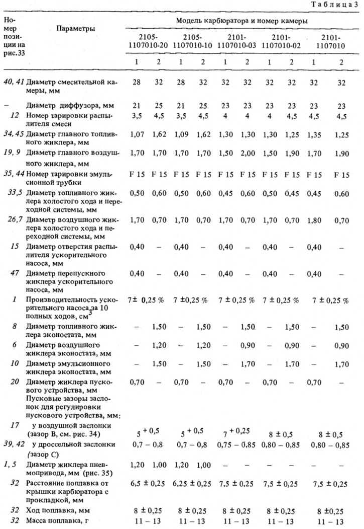
Carburettors with the corresponding ignition distributors are interchangeable with each other. The main data are given in table. 3.
Carburetor 2105-1107010-20
Emulsion type, double chamber, falling flow (pic. 32). It has a balanced float chamber, main dosing systems, enrichment device (econostat), idle system, transition system, diaphragm starter, crankcase exhaust spool, secondary chamber throttle pneumatic drive.
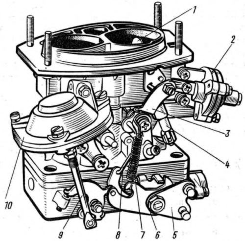
Pic. 32. Carburetor 2105-1107010-20:
1 - air damper; 2 - diaphragm starting device; 3 - three-arm lever; 4 - telescopic rod; 5 - throttle actuator lever of the first chamber; 6 - a lever that limits the opening of the throttle valve of the secondary chamber; 7 - return spring; 8 - rod connecting the throttle valve of the primary chamber with a three-arm lever; 9 - pneumatic drive rod; 10 - pneumatic actuator of the throttle valve of the secondary chamber.
Main dosing systems
Designed to prepare a combustible mixture of the required composition in throttling modes (small and medium engine loads), Fuel through needle valve 28 (pic. 33) enters the float chamber 4. The float 32 maintains the required fuel level. From the float chamber, the fuel enters the emulsion wells through the main fuel jets 34 and 45, mixes with the air leaving the holes of the emulsion tubes 35, 44 and entering them through the main air jets 9 and 19. Then, through the sprayers 12, the emulsion enters small and large carburetor diffusers.
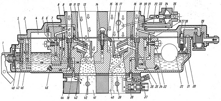
Pic. 33. Carburetor scheme:
1 - accelerator pump lever; 2 - adjusting screw; 3 - cork; 4 - float chamber; 5 - fuel jet of the transition system; 6 - econostat air jet; 7 - air jet of the transition system; 8 - econostat fuel jet; 9 - main air jet of the secondary chamber; 10 - emulsion jet econostat; 11 - econostat atomizer; 12 - atomizer of the main dosing system of the secondary chamber; 13 - small diffuser of the secondary chamber; 14 - screw valve of the accelerator pump; 15 - accelerator pump sprayer; 16 - small diffuser of the primary chamber; 17 - air damper; 18 - adapter bushings; 19 - main air jet of the primary chamber; 20 - starting device jet; 21 - thrust of the drive of the starting device; 22 - body of the starting device; 23 - stock; 24 - aperture of the starting device; 25 - adjusting screw of the starting device; 26 - idle air jet; 27 - needle valve seat; 28 - needle valve; 29 - filter; 30 - bracket with stop; 31 - damper ball; 32 - float; 33 - idle fuel jet; 34 - main fuel jet of the primary chamber; 35 - emulsion tube of the primary chamber; 36 - adjusting screw for the quality of the mixture; 37 - adjusting screw for the amount of the mixture; 38 - mixing sleeve; 39 - throttle valve of the primary chamber; 40 - primary mixing chamber; 41 - secondary mixing chamber; 42 - throttle valve of the secondary chamber; 43 - unregulated openings of the transition system; 44 - emulsion tube of the secondary chamber; 45 - main fuel jet of the secondary chamber; 46 - check valve of the accelerator pump; 47 - bypass jet of the accelerator pump; 48 - accelerator pump diaphragm.
The main fuel jets are 34 and are marked embossed on the side of the head (e.g. 107 or 162), which indicates the diameter of the orifice of the jet (1.07 or 1.62 mm). The main air jets 9 to 19 are marked on the upper plane (e.g. 170 or 190) and also indicate the diameter of the holes of the jets (1.70 or 1.90 mm). On the cylindrical surface of the emulsion tubes 35 and 44, a marking is applied that indicates the tube calibration number (e.g. 15). Small diffusers 13, 16 are also marked (e.g. 3.5 and 4.5), indicating the calibration number of the sprayer hole 12.
Econostat
Enriches the combustible mixture at maximum engine speeds, is included in the secondary chamber. Fuel from float chamber 4 (see fig. 33) through the fuel jet 8, the econostat enters the channels located in the carburetor cover, where air is mixed from the jet 6.
The air-fuel emulsion passes through the channel through the emulsion jet 10 and enters through the atomizer 11 into the diffuser. The econostat comes into operation at speeds close to the maximum, with fully open throttle valves.
Idle system
Prepares a rich hot mixture at engine idle. Fuel from the emulsion well enters jet 33 (see fig. 33) idle and mixes with the air entering through the air jet 26. Then, in the form of an emulsion, it passes through the emulsion channel and exits through the holes into the throttle space. The output of the emulsion is regulated by the mixture quantity screw 37 and the mixture quality screw 36. Exit hole above screws ensures no ''dip'" in the operation of the engine at the time of opening the throttle. To prevent violation of the factory idle speed adjustment, plastic restrictive bushings are pressed onto the screws 36, 37, which allow turning the adjusting screws only half a turn. Blue bushings are installed at the factory, and red at service stations.
Transitional system
Ensures no 'failures'" during engine operation at the beginning of opening the throttle valve of the secondary chamber and enriches the combustible mixture at the maximum speed of the engine (throttle valves open). Under the action of vacuum at the outlets 43 (see fig. 33) fuel from the emulsion well through the fuel channel, the fuel jet 5 of the transition system, mixing with air from the jet 7, enters the throttle space through the channel through the holes. On the cylindrical belt of the jet 5 there is a marking indicating the diameter of the jet hole.
Accelerator pump
Enriches the combustible mixture during a sharp opening of the throttle, providing good acceleration of the car. When the throttle is suddenly opened 39 (see fig. 33) the cam on the damper axis presses the lever 1 and through the pusher acts on the diaphragm 48, overcoming the resistance of the return spring. The diaphragm supplies fuel through the channel and injects through the atomizer 15 into the primary mixing chamber. Part of the fuel is passed through the bypass jet 47 back into the float chamber. The bypass jet is selected in such a way that when the throttle valve is opened smoothly, all the fuel is bypassed into the float chamber. The cam profile provides dual injection. The second injection coincides with the beginning of the opening of the throttle valve of the secondary chamber.
Sprayer 12 is marked (e.g. 40), indicating the diameter of the nozzle opening (0.40 mm).
Starting device
Provides a cold start engine. Consisting of air damper 2 (pic. 34) above the primary mixing chamber, three-arm lever 1, telescopic rod, throttle actuator rod 7 and diaphragm device. Lever 1 is connected by a rod to the manual control button in the passenger compartment under the instrument panel, When the button is pulled out, the three-arm lever through rod 7 slightly opens the throttle valve of the primary chamber, and the telescopic rod, turning the air damper lever, closes the air damper, Rod 3, connected to the air damper lever, moves along the groove of the rod 4 and occupies the extreme left position.
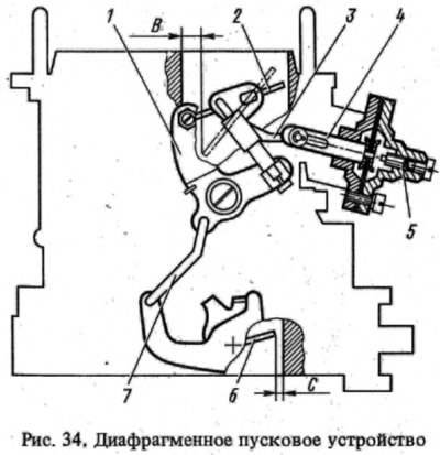
At the first flashes in the cylinders of a cold engine and subsequent idling, the vacuum from the throttle space is transmitted through the air channel to the cavity of the diaphragm mechanism. The diaphragm acts on the rod 4, rod 3 and slightly opens the air damper, providing the necessary composition of the combustible mixture. The spring in the telescopic rod allows the air damper to occupy intermediate positions depending on the magnitude of the vacuum in the throttle space. As the engine warms up, the choke is opened manually by a button from inside the car.
Pneumatic throttle valve of the secondary chamber
Designed for smooth activation of the main dosing system of the secondary chamber (pic. 35) and eliminating the need for a strong enrichment of the combustible mixture compared to carburetors with sequential opening of throttle valves. The pneumatic actuator automatically adjusts the damper position depending on the speed of the engine.

Pic. 35. Pneumatic throttle valve of the secondary chamber of carburetors 2105-1107010-20 and 2105-1107010-10:
1 - pneumatic drive jet located in the diffuser of the primary chamber; 2 - throttle actuator lever; 3 - lever rigidly connected to the axis of the throttle valve of the primary chamber; 4 - a lever that limits the opening of the throttle valve of the secondary chamber; 5 - pneumatic drive jet located in the diffuser of the secondary mixing chamber; 6 - lever connected to lever 9 through a spring; 7 - axis of the throttle valve of the secondary chamber; 8 - pneumatic drive rod; 9 - throttle control lever of the secondary chamber; 10 - channel for supplying vacuum to the pneumatic actuator; 11 - stem bushing; 12 - working cavity of the pneumatic actuator.
With the throttle valve of the first chamber open, with an increase in the load on the car, the crankshaft speed, and hence the vacuum in the mixing chambers, decrease, the secondary chamber damper is closed. The main air flow will pass through the primary mixing chamber, improving fuel atomization. With a sharp lowering of the throttle control pedal of the primary chamber, the damper of the primary chamber closes and lever 4 forcibly closes the throttle valve of the secondary chamber, preventing an increase in the crankshaft speed. The possibility of self-oscillation of the pneumatic drive mechanism is excluded by connecting cavity 12 with diffusers of both the secondary and primary mixing chambers through jets 1 and 5.
Carburetor control drive
Throttle valve opens from pedal 9 (pic. 36), which is mounted on the lever of the roller 12. The roller is mounted pivotally in two brackets 13, which are mounted on the front panel of the body. The levers are welded to the roller and the action from the lever 14 is transmitted to the longitudinal rod 2, the intermediate lever 15, the transverse rod 1 and then to the throttle actuator lever. Rods and 2 have plastic adjustable tips.
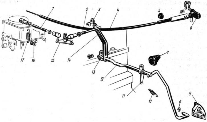
Pic. 36. Carburetor control drive:
1 - transverse thrust; 2 - longitudinal thrust; 3 - bracket for fastening the thrust; 4 - air damper control cable; 5 and 7 - seals; 6 - cable handle; 8 - lock washer; 9 - throttle control pedal; 10 - return spring; 11 - lever; 12 - roller; 13 - roller mounting bracket; 14 - lever; 15 - intermediate lever; 16 - screw for fastening the return spring; 17 - return spring.
The air damper is controlled by button 6, which is connected by a rod 4 to the air damper drive lever. The thrust shell is attached to the cover of the pneumatic actuator of the throttle valve of the secondary chamber. When the button is fully extended, the choke should be completely closed, and when it is recessed, it should be fully open.
Carburetor 2101-1107010-03
Differs from carburetors 2105-1107010-20 and 2105-1107010-10 in jet diameters (see table. 3) and the presence of heating of the throttle body. The sequential throttle carburetor does not have a secondary throttle valve actuator. The restrictive sleeve in the idle system is installed only on the mixture quality screw.
Carburetors 2101-1107010 and 2101-1107010-02
They differ from 2105-1107010-20, as well as from each other by the diameters of the jets. Sequential throttle carburetors have a float chamber unbalance valve and heated throttle bodies.
The float chamber imbalance valve facilitates starting a hot engine by preventing fuel vapors from entering the engine inlet, which can lead to excessive enrichment of the mixture and, therefore, difficult starting. When the throttle valves are closed, the float chamber is connected to the atmosphere through the valve. When the throttle valve is turned, the valve drive lever is released, and the valve, closing, separates the float chamber from the atmosphere.