




Fuel tank
It is welded from two halves stamped from a steel sheet. To increase corrosion resistance, the tank is lead-lined on both sides and painted black enamel on the outside. The fuel tank capacity is 39 liters, including a reserve of 4-6.5 liters. The tank is installed in the luggage compartment on the right side on a rubber gasket and secured to the body with clamps tightened with a bolt. The filler neck of the tank is brought out to a niche in the right rear wing and closed with a blind threaded plug. The tank is ventilated through a ventilation hose brought out to the filler neck hatch. Fuel located in the hose loop prevents gasoline from evaporating from the tank.
On VAZ-2105, VAZ-2107 and their modifications, fuel tanks 2101 are installed, on VAZ-2104, VAZ-21043 — fuel tanks 2102 with a capacity of 45 liters. Since 1985, drain plugs on fuel tanks have not been installed on all the cars under consideration.
Fuel lines
Made of galvanized or lead-coated steel tubes that are resistant to corrosion. The tubes are connected to each other, to the fuel tank intake pipe and to the fuel pump with rubber hoses in a fabric braid and secured with clamps. The fuel pump is also connected to the carburetor with a rubber hose.
[The text is taken from the online resource: VAZbook.ru]
Fuel pump
The diaphragm pump with a mechanical drive is installed on the left side of the cylinder block, secured on two studs through a heat-insulating spacer and adjusting linings, equipped with a lever 1 (Fig. 38) for manual fuel pumping. The pump capacity is not less than 60 l/h at a pumping frequency of 2000 cycles per minute. The pressure developed by the pump is 0.20-0.30 kgf/cm². All engines under consideration are equipped with a fuel pump from the 2101 engine.
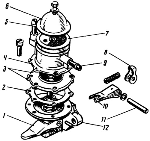
Fig. 38. Fuel pump:
1 - manual fuel pumping lever; 2 - external spacer gasket; 3 - diaphragms; 4 - upper body; 5 - discharge pipe; 6 - top cover; 7 - plastic mesh filter; 8 - mechanical fuel feed lever; 9 - suction pipe; 10 - balance beam; 11 - lever axis; 12 - lower body.
The fuel pump is driven by a pusher from the eccentric of the auxiliary drive shaft.
The pump consists of a lower housing 12 with drive levers, an upper housing 4 with valves and pipes, a diaphragm unit and a pump cover 6. The diaphragm unit is installed between the housings and has 3 diaphragms: two upper ones - working for fuel supply and a lower one - safety.
In the lower housing, on the axis 11, the lever 8 for mechanical fuel supply and the balancer 10 are installed. Also in the lower housing, on the axis with the cam, the lever 1 for manual fuel pumping into the carburetor is installed.
In the upper body of the 4 pumps, textolite hexagonal suction and discharge valves are installed.