

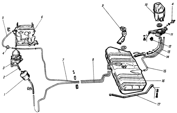
Pic. 39. Fuel tank and fuel lines:
1 - fine oil filter; 2 - fuel supply hose to the fuel pump; 3 - fuel pump; 4 - check valves; 5 - fuel drain hose from the carburetor; 6 - carburetor; 7 - fuel drain pipe; 8 - tube for supplying fuel from the tank; 9 - fuel level sensor; 10 - separator; 11 - separator mounting bracket; 12 - fuel tank cap; 13 - separator hose; 14 - filling pipe; 15 - filling pipe hose; 16 - fuel tank. 17 - tank fastening clamp.
Fuel supply - with a return drain of part of the fuel from the carburetor through a calibrated hole in the carburetor nozzle with a diameter of 0.7 mm back into the fuel tank. The performance of the fuel pump, which supplies fuel from the tank to the carburetor, exceeds the fuel demand of the engine. Constant circulation of fuel in the system removes air pockets and improves fuel supply reliability. The fuel tank 16 additionally plays the role of an engine cooler.
A check valve 4 is provided on the drain hose, which prevents fuel from draining from the tank through the carburetor when the vehicle rolls over.
The fuel tank is connected by a hose 13 to a separator 10, which serves to condense gasoline vapors. To prevent fuel from flowing out of the tank through the separator, a double-acting check valve is installed on the second separator hose. The valve works in both directions: as fuel is consumed from the tank, it passes atmospheric air into the tank, and when the pressure in the tank rises, it releases fuel vapors from the tank.
The air supply is carried out through a thermostat, an air filter, a carburetor, from which the air in the composition of the combustible mixture enters the engine cylinders through the inlet pipeline. Exhaust gases are released into the atmosphere through the exhaust manifold, exhaust pipe, additional and main mufflers.