




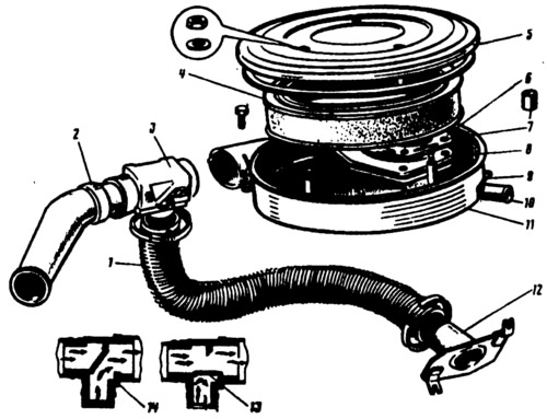
Fig. 39. Air filter:
1 - warm air intake hose; 2 - cold air intake; 3 - thermostat; 4 - filter element; 5 - lid; 6 - filter mounting plate; 7 - spacer sleeve; 8 - gasket; 9 - branch pipe for removing crankcase gases into the throttle space; 10 - crankcase exhaust manifold; 11 - Air filter housing; 12 - warm air intake; 13 - thermostat flap; 14 - thermostat housing.
The thermostat consists of a plastic housing with a flap 13, the position of which can be changed by manually moving the handle. Depending on the ambient temperature, the handle can be set to one of three positions: HOT - for taking in warm air through the air intake 12; COLD — for cold air intake through intake 2; intermediate position, when the damper is in the middle position and air is sucked in through both intakes.
The vehicles in question may be equipped with thermostats with automatic damper drive from a thermal power element installed in the thermostat housing and providing automatic opening and closing of the thermostat damper, maintaining the air temperature at the air filter inlet of 32-42°C. On top of this thermostat there is an additional pneumatic damper drive connected by a hose to the cavity of the intake manifold. When idling, due to the increased vacuum in the intake manifold, the damper will be in the open position, which ensures the flow of warm air into the engine to achieve more complete combustion of the working mixture and reduce the toxicity of the exhaust gases.
Intake pipe
The inlet pipe is cast iron, it is attached to the cylinder head studs through two sealing ferronite gaskets, common with the exhaust manifold. The sealing gaskets and fastening nuts are disposable.
The original source is published on the website: www.vazbook.ru
The intake pipe has a platform for installing the carburetor and four channels for feeding the working mixture into the engine cylinders. The pipe has a mixture heating jacket, which is connected by channels to the cylinder head cooling jacket. The fluid is removed from the heating jacket of the intake pipe through a hose and tube 1 (see fig. 27) to the coolant pump 15.
The gasoline condensate formed on a cold engine is drained from the intake manifold to the outside through the drain pipe. To prevent a noticeable leaning of the mixture at idle, the drain pipe has an outlet opening with a diameter of (0.8±0.1) mm.